
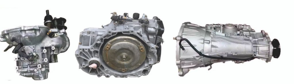
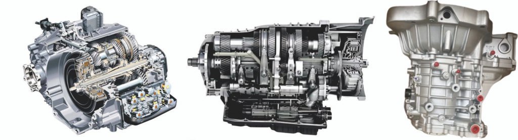
Modern sedan transmissions are highly integrated, precision components, primarily categorized into four main types: Manual (MT), Hydraulic Automatic (AT), Continuously Variable (CVT), and Dual-Clutch (DCT), each with distinct structures.
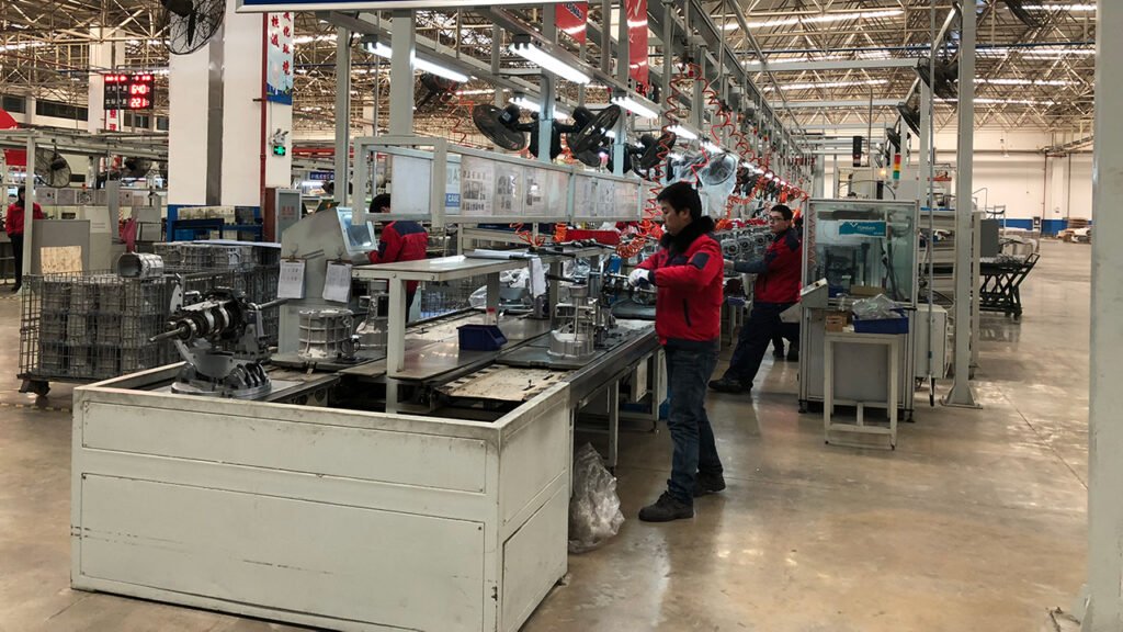
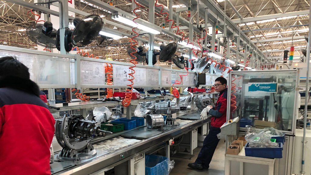
Their production relies on highly automated, data-driven intelligent assembly lines. The process encompasses three major stages: sub-assembly pre-assembly, main line final assembly, and end-of-line testing, all conducted in a cleanroom environment with emphasis on torque control and clearance measurement. The production line extensively utilizes robots, servo tools, and AGV material handling, achieving full-process data traceability through an MES system.
Before leaving the line, each transmission must pass rigorous leak tests and dynamic functional tests that simulate real-world operating conditions to verify shift quality, NVH, and hydraulic/electrical performance. The industry is advancing towards “zero-defect” quality goals, human-robot collaboration, and deeply integrated assembly for electric drive systems, reflecting the cutting-edge level of automotive manufacturing.
Gearbox Assembly Lines are suitable to Assemble/Produce gearboxes. (If clients have more requirements or want to produce the other gearboxes, welcome to contact us.)
Part I. Structure, Assembly, and Testing Processes of Sedan Transmissions
Sedan transmissions, especially mainstream automatic ones, are among the most technologically complex and precise components in an automobile.
I. Main Structures of Sedan Transmissions
Modern sedan transmissions are primarily divided into four main types, with significant differences in their core structures:
1. Manual Transmission
- Core Structure:
- Input/Output Shafts: Transmit power.
- Countershaft/Layshaft: Holds fixed gears of different sizes.
- Synchronizer: The core component that synchronizes the speed of gears and the shaft before shifting to prevent grinding.
- Shift Fork and Slider: Driven by the shift lever to push the synchronizer sleeve for gear engagement.
- Clutch Assembly: Engages/disengages with the transmission to transmit engine power.
- Characteristics: Relatively simple structure, direct mechanical connection, high efficiency.
2. Hydraulic Automatic Transmission
- Core Structure:
- Torque Converter: Replaces the clutch, flexibly transmits power via hydraulic fluid, provides torque multiplication and damping.
- Planetary Gear Set: The core transmission mechanism. Fixing or engaging different elements (sun gear, planet carrier, ring gear) achieves multiple gear ratios.
- Multi-Plate Clutches/Brakes: Controlled hydraulically to lock or engage specific elements of the planetary gear set.
- Hydraulic Control System: Includes oil pump, valve body, solenoid valves, fluid passages. The valve body is the “hydraulic brain,” regulating pressure and flow based on electronic signals.
- Electronic Control Unit: Receives vehicle sensor signals, controls solenoid valves to determine shift timing and quality.
3. Continuously Variable Transmission
- Core Structure:
- Primary/Secondary Pulley Sets: Each set consists of a fixed and a movable conical sheave, allowing the V-shaped groove width to change.
- Steel Belt or Chain: Connects the two pulley sets. Changing the contact radius achieves a continuous, stepless change in the gear ratio.
- Hydraulic System: Controls pulley clamping force (to prevent belt slip) and position (to change the ratio).
- Launch Device: Often a torque converter or wet multi-plate clutch to ensure smooth launch.
4. Dual-Clutch Transmission
- Core Structure:
- Two Concentric Input Shafts: One hollow, one solid, connected to odd and even gears respectively.
- Two Independent Dry or Wet Clutches: Control the engagement/disengagement of the two input shafts separately.
- Two Parallel Gear/Synchronizer Systems: Correspond to odd and even gears respectively.
- Complex Mechatronic Control Module: Integrates hydraulic unit, sensors, and ECU, precisely controlling the “pre-engagement” and disengagement of the two clutches for millisecond-level shifts.
II. Assembly Process (Using AT/DCT as Examples)
Core Process Flow:
- Housing and Valve Body Cleaning:
- All components must undergo rigorous ultrasonic cleaning and high-pressure rinsing before assembly to ensure no metal debris or dust remains.
- Sub-Assembly:
- Planetary Gear/Gear Shaft Sub-Assembly: Precision assembly of planetary gears, clutch plates, bearings, thrust washers, etc., into a module using dedicated fixtures.
- Valve Body Sub-Assembly: Installing precise solenoid valves, spool valves, springs, etc., into the valve body, followed by initial functional tests (e.g., leak testing).
- Main Assembly Line:
- Housing Loading: Fixed onto a rotatable automated assembly pallet.
- Internal Component Assembly: Robots or automated stations sequentially install the oil pump, input/output shafts, planetary gear sets/gear sets, multi-plate clutches, etc. Torque control and clearance measurement are critical, extensively using servo electric guns and sensors.
- Valve Body and Harness Installation: Mounting the “brain” (valve body) and “nervous system” (wire harness assembly).
- Oil Filling and Sealing:
- Adding the specified type and volume of dedicated transmission fluid.
- Installing the oil pan, with robots often applying sealant to ensure leak-tightness.
- Final Assembly:
- For ATs, pushing the torque converter into place and locking it.
- Final cleaning and protection of all external interfaces of the transmission.
III. Testing Processes
Testing runs through the entire product lifecycle: design verification, production process, end-of-line, and after-sales.
1. Component-Level Testing
- Dimensional and Geometric Accuracy: Using Coordinate Measuring Machines for full-dimensional inspection of critical parts (e.g., housings, valve bodies, gears).
- Material and Hardness: Spectrographic analysis, metallographic inspection, hardness testers.
- Cleanliness Testing: Filtering and weighing residue from cleaned parts to check for contaminant particle weight and size.
2. Sub-Assembly Testing
- Valve Body Test Bench: Simulates hydraulic pressure and electrical signals to test flow, pressure response, and solenoid valve actuation for each circuit, ensuring no leaks and accurate response.
- Clutch/Brake Testing: Tests for seal integrity, piston stroke, and engagement characteristics.
3. End-of-Line Testing (100% Testing)
- Leak Test: Pressurizing the transmission with compressed air or nitrogen to detect leaks in the housing, seals, etc.
- Dynamic Functional Test:
- No-Load Test: On a test bench, a motor drives the transmission input shaft, simulating various speeds and loads, checking:
- Shift Timing and Smoothness: Using speed sensors to determine if shifts complete within specified time.
- Noise and Abnormal Sounds: NVH analysis using microphone arrays.
- Oil Pressure and Temperature: Ensuring pressures for all gears are within specification.
- Leak Re-check: Inspecting for seepage after the test.
- Load/Drag Test: A more advanced test applying realistic loads using electric inertia simulators to evaluate shift quality, slip rate, transmission efficiency, and thermal balance.
4. Sampling and Type Testing
- Sampling Endurance Bench Test: Samples from production batches undergo accelerated cycle testing on benches far exceeding equivalent vehicle life, assessing reliability and wear.
- Vehicle Road Testing: Installing transmissions in vehicles for real-world road tests under extreme conditions like high temperature, extreme cold, high altitude, and mountainous terrain.
Part II. Sedan Transmission Assembly Line
I. Core Characteristics of the Assembly Line
- High Cleanliness Environment: Assembly takes place in a clean room with constant temperature and humidity to prevent dust and foreign particles from contaminating precision components.
- High Precision and Consistency: Extensive use of servo fastening systems, vision guidance, and automatic measurement technologies ensures that every bolt’s torque and every component’s clearance strictly adhere to process requirements.
- High Automation and Flexibility: Industrial robots, and automated special-purpose machines are widely used. A single line is typically capable of mixed-model production for various transmission types within the same platform.
- Full-Process Data Traceability: Each transmission is assigned a unique identifier (e.g., RFID or QR code). All critical data—from component loading to final assembly—including torque, pressure, measurements, operator, and test results, is collected in real-time and linked to this identifier, enabling lifecycle traceability.
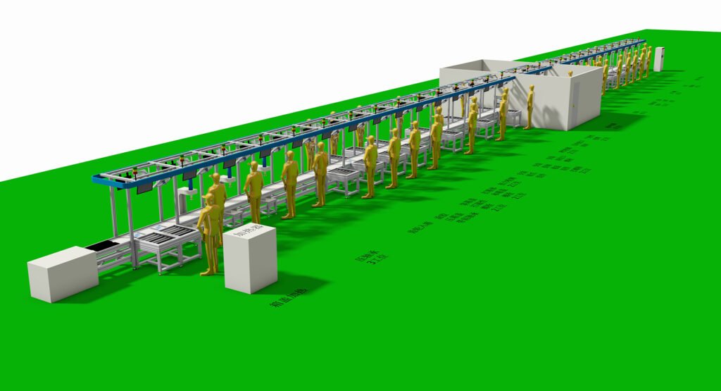
II. Main Stages and Process Flow of the Assembly Line
A complete transmission assembly line typically consists of the following core stages in sequence:
1. Pre-Assembly / Sub-Assembly Stage
- Objective: Pre-assemble small components into modular sub-assemblies to improve mainline assembly efficiency and accuracy.
- Key Processes:
- Valve Body Assembly and Testing: Precision solenoid valves, spool valves, and springs are assembled by robots or high-precision equipment within ultra-clean workstations. Upon completion, immediate functional and leak testing is conducted on a valve body test bench to ensure the “hydraulic brain” is qualified.
- Planetary Gear/Gear Shaft Module Assembly: Components such as planetary gear sets, multi-plate clutches, bearings, and spacers are pre-assembled into an integrated module using dedicated fixtures. Axial clearance measurement and adjustment are critical in this process.
- Torque Converter Assembly: Assembly of the lock-up clutch, fins, etc.
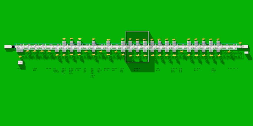
2. Main Assembly Line Stage
- Objective: Complete the core assembly of the transmission housing.
- Carrier: The transmission housing is typically placed on an automated, liftable/rotating pallet to facilitate optimal assembly angles for workers or robots.
- Key Process Sequence:
- Housing Loading and Identification: An empty housing is loaded, and an RFID reader identifies its model, calling up the corresponding assembly program.
- Installation of internal components such as the oil pump and oil passages.
- Shaft and Gear Set Installation: Robots or automated hoisting equipment precisely place the pre-assembled planetary gear module or input/output shaft assembly into the housing. Servo presses ensure proper installation without damage.
- Sensor and Harness Installation: Installation of speed and temperature sensors, as well as the vehicle interface harness.
- Valve Body Assembly Installation: Mounting the tested and qualified valve body assembly onto the housing and connecting the hydraulic circuits.
- Oil Pan Installation: A robot automatically applies sealant, followed by installation of the oil pan. Servo nutrunners tighten the bolts in a specified sequence and to the required torque.
- Torque Converter Installation: For automatic transmissions, the torque converter is pushed into place and locked.
- Transmission Fluid Fill: A high-precision, quantitative filling system injects the specified type and volume of dedicated fluid.
3. Functional Testing and Final Stage
- Objective: Conduct 100% final verification of the fully assembled transmission.
- Key Processes:
- Leak Test / Pressure Decay Test: The transmission is pressurized with gas to detect any leaks from the housing, seals, etc.
- Dynamic Functional Test (Core Step):
- The transmission is transported to a fully enclosed test cell.
- A test bench motor connects to the transmission via half-shafts.
- Various vehicle operating conditions are simulated: launch, upshifts, downshifts, coasting, park, etc.
- Monitored Parameters:
- Shift Quality: Calculated from input/output shaft speed sensors to determine shift time and smoothness (shift shock).
- NVH (Noise, Vibration, Harshness): Analysis for abnormal sounds using microphones and accelerometers.
- Hydraulic System: Monitoring whether oil pressures for all gears are within the calibrated range.
- Electrical Functions: Verifying all sensor and solenoid valve signals are normal.
- Final Inspection and Cleaning: After passing tests, a final visual inspection is conducted, the exterior is cleaned, and a conformity label is applied.
III. Core Supporting Technologies and Systems
- Manufacturing Execution System (MES): Acts as the “central nervous system” of the assembly line, responsible for production scheduling, issuing process instructions, collecting and analyzing quality data, and monitoring equipment status.
- High-Precision Tools: Servo fastening spindles, vision guidance systems, automatic sealant applicators, clearance gauges, etc.
- Material Handling System: Utilizes AGVs or SPS (Set Parts Supply) carts to deliver components to workstations just-in-time and accurately based on production takt time, reducing human picking errors.
- Andon System: Allows operators to stop the line and call for support if quality, equipment, or material issues arise, preventing problems from propagating to the next station.
IV. Development Trends
- “Zero-Defect” Quality Goal: Leveraging big data from tests and AI prediction to identify potential assembly deviations early, shifting from “detecting defects” to “preventing defects.”
- Human-Robot Collaboration: Collaborative robots share workspace with operators, handling repetitive, heavy, or high-precision assembly tasks.
- Deeply Integrated Assembly: With the rise of electric vehicles, the assembly of the motor, inverter, and reducer (3-in-1 E-drive) is being consolidated into more integrated electric drive unit assembly lines.
- Digital Twin: Creating a complete digital model of the assembly line in a virtual world for process simulation, optimization, and employee training, which is then mapped to the physical production line.
Summary
The modern sedan transmission assembly line is far more than a simple parts assembly line; it is a data-driven, highly intelligent, self-optimizing precision manufacturing system. It ensures that every transmission leaving the line possesses excellent performance, high reliability, and consistency, representing a concentrated embodiment of the advanced manufacturing capabilities within the automotive industry.
We can customize according to the client’s product specifications, production capacity or other requirements.
We provide comprehensive services including design, production, and installation/commissioning.