Reel Push Mower Assembly Line—Push Lawn Mower Assembly Line—Walk-behind Lawn Mower Assembly Line
A push reel mower is a purely mechanical lawn trimming tool. Its core working principle is the “Scissor Effect”: when pushed forward, the rotating reel blades and the fixed bottom blade create a shearing motion to cut the grass like scissors. Key modules include: the frame and housing, the core cutting system (reel, moving blades, and bottom blade), the drive/walking system (rear wheels with a one-way clutch), the height adjustment system, and an optional grass catcher.
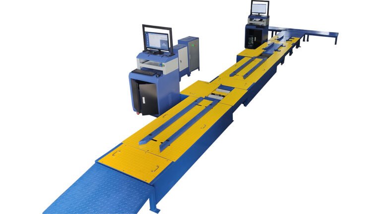
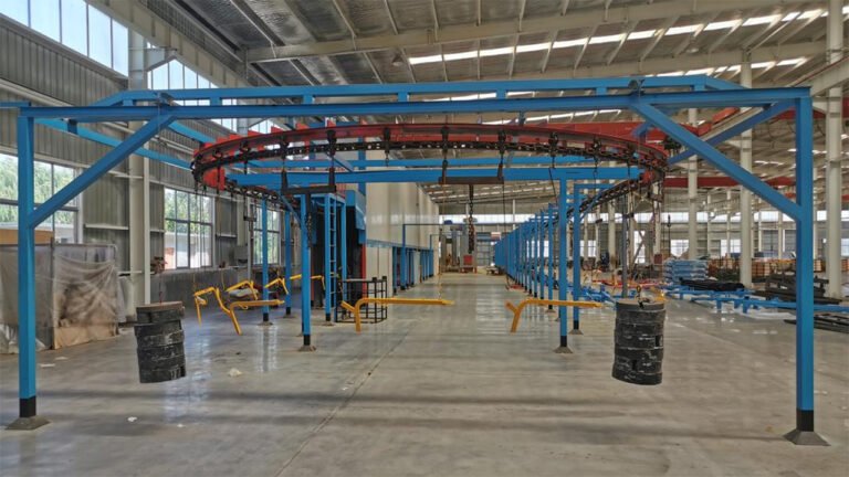
The differential chain-drive lawn mower assembly line adopts a U-shaped modular or linear layout, with precision differential assembly at its core. Key processes involve chain tensioning control and multi-system (power, transmission, cutting) integration. The production process can incorporate data traceability (e.g., torque, tension) and information management (MES systems), with multi-station dynamic testing (such as differential function and roller dynamometer tests) ensuring overall machine performance. The line is designed with flexibility to accommodate production of both gas and electric models.
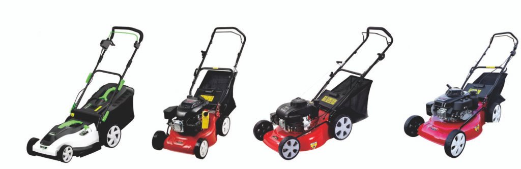
Push Lawn Mower Assembly Lines are suitable to Assemble/Produce Mowers. (If clients have more requirements or want to produce the other Mowers, welcome to contact us.)
Part I: Structure, Assembly, and Testing Process for Push Lawn Mowers
I. Main Structure and Functions
A push reel mower is a purely mechanical lawn trimming tool. Its core working principle is the “Scissor Effect”: when pushed forward, the rotating blades on the reel and the fixed bottom blade create a shearing motion, cutting the grass like scissors.
Main components can be divided into several key modules:
- Frame & Housing
- Main Frame: Typically made from high-strength steel tubing or stamped steel plate, forming the skeleton that connects all components.
- Side Panels / Housing: Protects internal mechanisms, directs grass clippings, and ensures safety.
- Handle: Connects to the main frame, often height-adjustable (on premium models), for pushing. Usually “U” or “D” shaped.
- Cutting System (Core)
- Reel (Cylinder): A cylindrical drum with 5-6 spiral blades (reel blades) mounted along a helix. The reel rotates on bearings mounted in the frame.
- Reel Blades (Moving Blades): Sharp, thin, curved steel blades that rotate with the reel.
- Bottom Blade (Bed Knife / Fixed Blade): A straight, sharp steel bar fixed horizontally across the front bottom of the mower. Its position is finely adjustable. It forms the cutting couple with the reel blades.
- Drive Gear Set: Located at one end of the reel, transfers power from the wheels to the reel.
- Drive/Walking System
- Front Wheels (Small): Usually a pair, smaller in diameter, primarily for steering.
- Rear Drive Wheels (Large): Usually a pair, larger in diameter. The axle connects to the drive gear via a one-way clutch (overrunning clutch). Pushing forward engages the clutch, driving the gears; pulling backward disengages it, allowing easy reversal without driving the blades.
- Axles & Bearings: Support the wheels for smooth rolling.
- Height Adjustment System
- Adjustment Mechanism: Common types include single-point central adjustment or four-wheel independent adjustment. A lever or knob moves a linkage or plate, changing the height of the frame (and bottom blade) relative to the ground, thus setting the cutting height.
- Adjustment Plate / Notches: Features multiple detent positions corresponding to different cutting heights (e.g., 20mm-60mm).
- Grass Catcher (Optional)
- Box/Bag: Attaches to the rear of the mower to collect clippings.
- Adapter / Connector: Ensures a secure fit between the catcher and the mower’s discharge chute.

II. Assembly Process Flow
The assembly line typically follows an inside-out, core-to-peripheral principle, using a conveyor system.
- Preparation & Line Feeding
- All parts (frame, reel, wheels, gears, etc.) undergo quality inspection before being delivered to workstations according to the sequence.
- Standard parts (screws, washers, circlips, etc.) are supplied via bins or automatic feeding systems.
- Core Module Pre-Assembly
- Cutting Unit Assembly: Reel blades are mounted onto the reel according to the specified helical angle and sequence, then secured. Bearings are then pressed into both ends of the reel.
- Gearbox Assembly: Gears, clutch, bushings, etc., are assembled into the gearbox housing with an appropriate amount of lubricating grease.
- Wheel Assembly: Wheels, washers, and retaining rings are mounted onto axles.
- Main Frame Final Assembly
- Frame Positioning: The main frame is secured in an assembly fixture.
- Installing Cutting System: The assembled reel unit is installed onto the frame via bearing housings. The bottom blade is then installed, and its clearance with the reel blades is roughly pre-adjusted (typically to approx. 0.1mm using a feeler gauge).
- Installing Drive System: The front wheel set and rear wheel set (with axle) are installed onto designated frame positions. The output end of the rear axle is connected to the gearbox input.
- Installing Transmission: The pre-assembled gearbox unit is installed onto the frame, ensuring proper gear mesh with the reel gear. The connection to the rear axle is finalized.
- Installing Adjustment System: The height adjustment linkage, lever, springs, etc., are installed onto the frame and wheel axles.
- External Attachment Installation
- Side panels/housing are installed.
- Handle tubes are installed, and height adjustment cables are connected (if applicable).
- Grass catcher adapter is installed.
- Final Assembly & Adjustment
- Grass catcher is installed.
- All decorative covers, labels, manual pouch, etc., are installed.
- Critical Step: Fine-tuning Bottom Blade Clearance. Using specialized tools or a feeler gauge, ensure the clearance between all reel blades (as they pass the bottom blade) and the bottom blade is uniform (typically “just touching” or a clearance of 0.03-0.1mm). This is crucial for cutting performance and ease of use.
III. Inspection & Testing Process
Every finished mower must undergo rigorous inspection for safety and performance.
- Visual & Dimensional Inspection
- Check housing for scratches, dents, or stains.
- Verify all fasteners are tightened and none are missing.
- Check labels for correctness and secure attachment.
- Safety & Functional Tests
- Reel Rotation Smoothness Test: Lift the mower and rotate the rear wheels. Check that the reel rotates smoothly and easily without binding or unusual noise.
- Clutch Function Test:
- Forward Test: Rotating the rear wheels forward must cause the reel to rotate synchronously.
- Reverse Test: Rotating the rear wheels backward should NOT drive the reel (or allow only minimal inertial movement), ensuring blades don’t operate when pulling back. This is a mandatory safety check.
- Height Adjustment Test: Operate the adjustment lever to ensure all positions engage clearly and smoothly, and the frame raises/lowers evenly and locks.
- Blade Safety Check: Inspect that all reel blades are securely fastened, not loose. Manually check (often with protective gloves) that edges are sharp but free of burrs.
- Cutting Performance Test (Sampling or 100% Check)
- Push the mower on a test stand (simulated turf brush or special test belt) to check for continuous, smooth cutting action.
- Listen for sound quality; gear mesh and cutting should sound even (a uniform “swishing” sound, no metal clashing or high-pitched scraping).
- Dynamic Balance Test (High-end models): Test vibration amplitude during high-speed reel rotation to ensure smooth operation.
- Final Check & Packaging
- Clean the mower, removing any oil, grease, or fingerprints.
- Perform final lubrication on all moving parts (gears, bearings, adjustment points).
- Place in a plastic bag, pack into carton with accessories (e.g., oil, tools), and user manual.
- Conduct packaging drop tests (sampling) to ensure transportation safety.
Part II: Push Lawn Mowers Assembly Line—Assembly Line for Differential Chain-Drive Lawn Mowers
I. Product and Process Analysis
- Typical Product Structure:
- Chassis Assembly: Includes frame, handlebar, engine/motor mounting bracket.
- Power System: Gasoline engine or high-power brushless motor.
- Transmission System: Core component. Includes gearbox (differential), drive shaft, chain, sprockets, tensioning mechanism.
- Cutting System: Blade disc, blades (or nylon line trimmer head), protective shield.
- Travel System: Drive wheels (left/right), idler wheels, axles.
- Control System: Clutch/throttle cables, switches, height adjustment lever.
- Core Assembly Process Characteristics:
- High Precision Required for Differential Assembly: Gear meshing and bearing preload are critical, directly affecting steering flexibility and lifespan.
- Chain Tensioning is Key: Tension must be adjustable and reliable; incorrect tension causes issues.
- Multi-Shaft Alignment: Drive wheels, idler wheels, and blade disc must maintain relative positioning to ensure straight travel and cutting.
- Dynamic & Static Testing: Requires no-load operation, differential function, cutting balance tests.
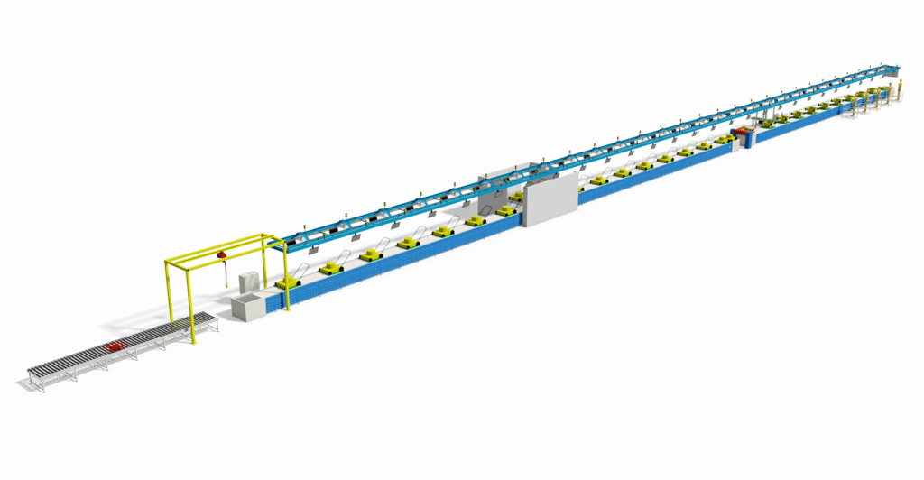
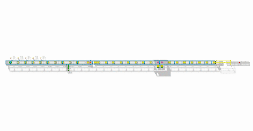
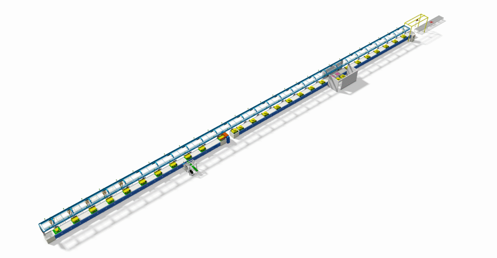
II. Overall Assembly Line Layout Design
A “U-shaped” or “mixed-model straight-line” layout with modular design is recommended
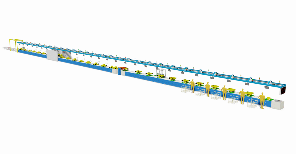
- Layout Diagram:
[Material Loading Area] -> [Frame Pre-treatment Segment] -> [Chassis Assembly Segment] -> [Power & Transmission Assembly Segment (Core)] -> [Cutting & Travel System Installation Segment] -> [Appearance & Control Parts Installation Segment] -> [Final Debugging & Testing Segment] -> [Packaging & Offline Area] (Reverse Flow) (Logistics Aisle) (Reverse Flow)- Advantages: Short material flow, facilitates collaboration, adaptable to multi-model variable-volume production.
III. Detailed Core Workstations & Equipment
- Segment 1: Frame Pre-treatment & Chassis Assembly
- Station 1: Frame loading, barcode scanning. Automated hoist or AGV transport.
- Station 2: Critical Fastening Station. Uses multi-spindle bolt tightening machines to install bolts for key stress points (engine mounts, differential housing brackets). Data is traceable.
- Station 3: Install fuel tank (gas models), battery compartment (electric models), pre-route wiring harness.
- Segment 2: Power & Transmission System Assembly (Core Segment)
- Station 4: Differential Unit Assembly Sub-line.
- Press-fit bearings into differential housing.
- Install planetary gears, side gears.
- Add grease, join housing halves and fasten. Uses dedicated fixtures to ensure concentricity.
- Station 5: Differential-Frame Marriage. Hoist and mount the differential assembly to the frame, connect and secure. Uses torque wrenches.
- Station 6: Engine/Motor Installation. Mount the power source to its bracket and connect it to the differential input shaft via a coupling or belt (initial connection).
- Station 7: Chain Drive System Installation.
- Install output sprocket on differential, drive axle sprocket.
- Mount the chain.
- Install automatic tensioner or manual adjustable idler sprocket. This station requires a chain tension meter to ensure tension is within specification.
- Station 4: Differential Unit Assembly Sub-line.
- Segment 3: Travel & Cutting System Installation
- Station 8: Install drive wheels, idler wheels, adjust cutting height lever mechanism.
- Station 9: Install blade disc assembly, protective shield. Dynamic balance check is required here (for metal blades) to prevent high-speed vibration.
- Station 10: Install drive shaft (for direct blade drive) or belt/another chain set (if power is separated).
- Segment 4: Final Assembly & Debugging
- Station 11: Install handlebar, control panel, all control cables (throttle, clutch, blade clutch), connect wiring harnesses.
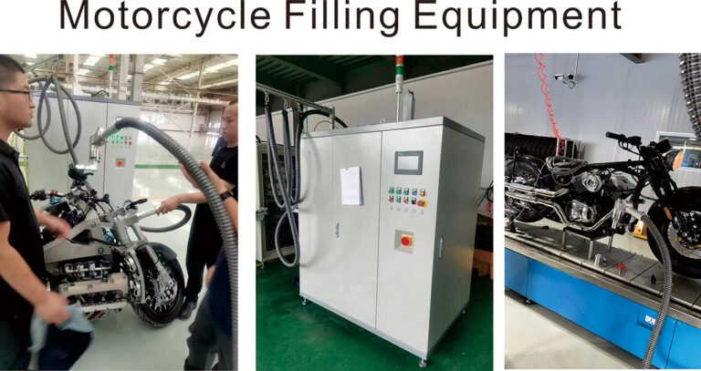
- Station 12: Add engine oil (gas models), coolant (if required).
- Station 13: Critical Debugging Station.
- Differential Function Test: Lift the mower, start it, and gently rotate one wheel to observe if the opposite wheel rotates smoothly in the opposite direction.
- Chain Operation Test: Observe if the chain runs smoothly without abnormal noise or skipping.
- Cutting Mechanism No-load Test: Engage the blade disc, check for vibration and abnormal noise.
- Travel Function Test: Test all gear speeds on a roller dynamometer.
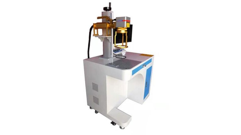
- Station 14: Final inspection, labeling, cleaning.
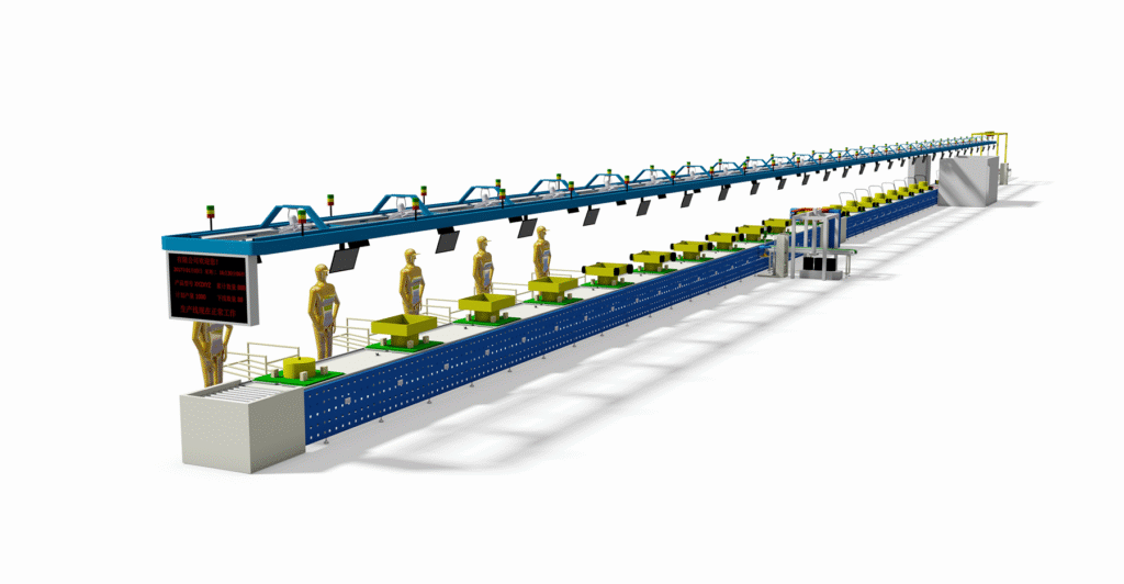
IV. Logistics & Information Management
- Material Supply: Use Set Parts Supply (SPS) or AGV point-to-point delivery to deliver large parts (engine, differential unit, wheels) directly to corresponding stations.
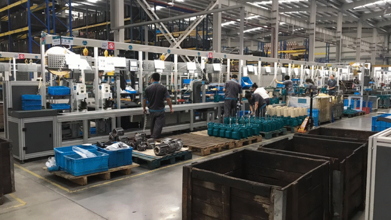
- Conveyor Type: Use friction roller conveyors with lift & stop units or slat conveyors for high load capacity and adjustable speed.
- Information Management:
- Each product has a unique QR code recording key torque values, tension data, and test results.
- Andon System: Instant light/pull-cord alarm for quality or material issues at any station.
- Final test data is uploaded to the MES system, creating a product “electronic record.”
V. Key Quality Control Points
- Differential Unit: Gear backlash, rotational resistance torque.
- Chain Tension: Measured with calibrated tools, data recorded.
- Critical Bolt Torque: Frame, differential, engine mounting bolts. All tightened with electric tools, data traceable.
- Blade Disc Dynamic Balance: Mandatory balancing for high-speed metal blades.
- Final Run-in Test: Simulates real operating conditions to check for noise, overheating, leaks.
VI. Capacity & Flexibility Design
- Cycle Time Calculation: Calculate takt time based on target annual output (e.g., 50,000 units/year) to determine the number of workstations.
- Flexibility Design:
- Quick-change fixtures and tooling adapt to different frame models.
- Power assembly stations compatible with both gas and electric versions.
- Debugging programs automatically call up corresponding parameters based on the model.
Summary
The core of a differential chain-drive lawn mower assembly line lies in ensuring the precise assembly and reliable debugging of the differential transmission system. An excellent assembly line is not just about putting parts together; it is a system for quality manufacturing and testing. It achieves this through:
- Modular Design to separate complex assemblies.
- Specialized Tools to guarantee critical processes (torque, tension).
- Information Traceability for quality control.
- Comprehensive Testing to ensure the performance of every finished product.
Such a production line significantly improves product consistency, reliability, and production efficiency while reducing post-sale failure rates.
We can customize according to the client’s product specifications, production capacity or other requirements.
We provide comprehensive services including design, production, and installation/commissioning.