
As a complex agricultural machinery, the power tiller‘s structural core lies in its high-power engine system and multi-stage transmission assembly (including differential/steering mechanism). Assembly focuses on precision gearbox assembly and rigid engine-transmission connections, with load testing ensuring reliability under harsh operating conditions.
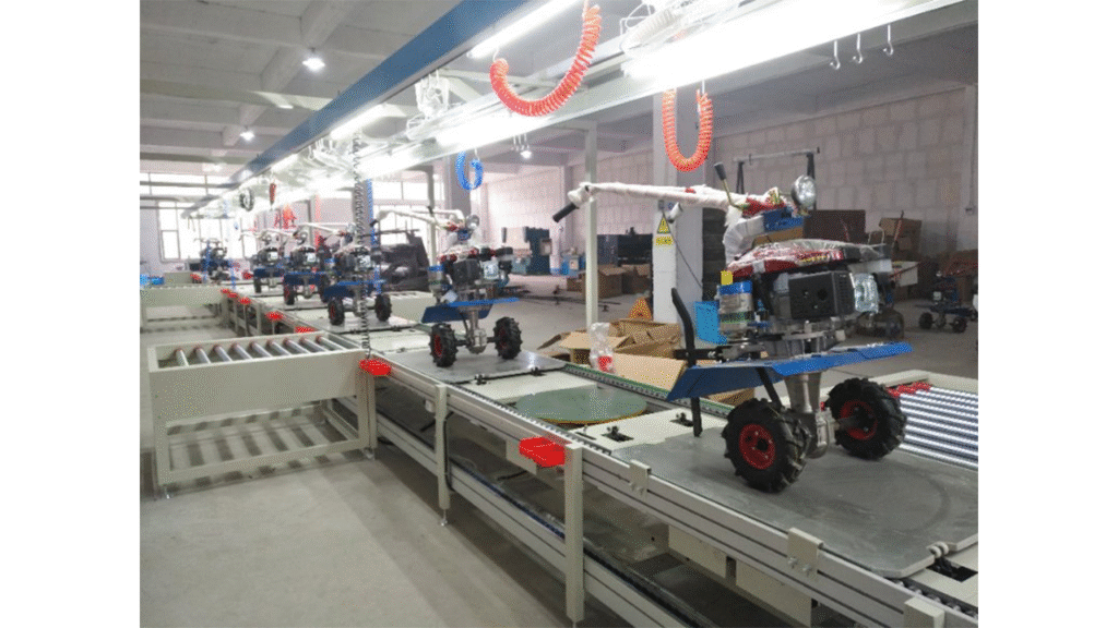
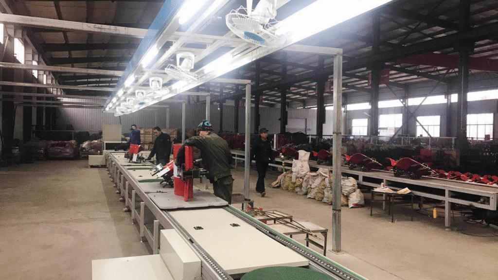
The corresponding large-scale linear power tiller assembly line employs a rigid process design, following a fixed operational sequence to achieve stable takt time. Through parallel operation of dedicated gearbox and main host assembly lines, combined with heavy-duty conveying systems and online quality monitoring, it significantly enhances production efficiency while ensuring transmission system assembly accuracy. This production line is suitable for large-scale manufacturing of standardized platform products.
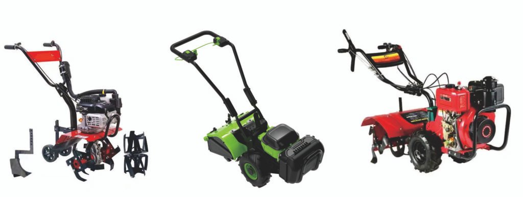
Power Tiller Assembly Lines are suitable to Assemble/Produce Power Tillers. (If clients have more requirements or want to produce the other Power Tillers, welcome to contact us.)
Part I: Power Tiller: Structure, Assembly, and Inspection Process
I. Product Structure and Functional Modules
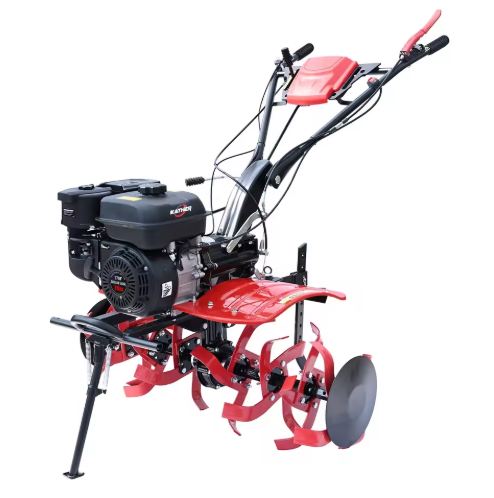
The power tiller is a compact, multifunctional agricultural power machine primarily used for rotary tilling, trenching, ridging, and weeding in small plots such as dry fields, orchards, and vegetable gardens. Its design features a compact structure, powerful output, complex transmission, and suitability for harsh working conditions.
- Power System
- Engine: Typically an air-cooled single-cylinder diesel engine or a high-power gasoline engine providing primary power. Diesel engines dominate professional models due to their high torque and rugged durability.
- Fuel System: Fuel tank, fuel lines, filter.
- Intake and Exhaust Systems: Air cleaner (dry or oil-bath type, requiring high dust resistance), muffler.
- Starting System: Recoil pull-start or electric start.
- Transmission and Travel System (Core & Most Complex Part)
- Main Clutch: Often a belt-tension centrifugal clutch or friction disc clutch located at the engine output.
- Gearbox: Core component. Usually a combined gearbox integrating:
- Gear Sets: Provide multiple forward gears and 1-2 reverse gears.
- Central Drive: Bevel gear set redirecting power by 90 degrees.
- Differential/Steering Clutch: Key mechanism for steering. Two main types:
- Dog Clutch Differential: Provides positive steering via engagement/disengagement of clutch jaws; simple and reliable.
- Friction Disc Steering Clutch: Provides softer steering by disengaging power to one side.
- Final Drive: Secondary or tertiary reduction gears drastically reducing speed and increasing torque to operational levels.
- Drive Axle: Outputs high torque to drive tires or steel lug wheels.
- Travel Wheels: Options include rubber tires (transport) or steel lug wheels (for increased traction).
- Working and Control System
- Rotary Tine Shaft: Rotating shaft mounting the tines, driven by the gearbox via chain or gears.
- Rotary Tines: Helically arranged “L-shaped” or “right-angle” blades, the primary working components.
- Depth Stake/Balance Bar: Used to adjust tilling depth and balance the machine.
- Control Assembly: Includes handlebars, all control linkages (clutch, throttle, gear shift, steering clutch), and protective covers.
II. Assembly Process Flow
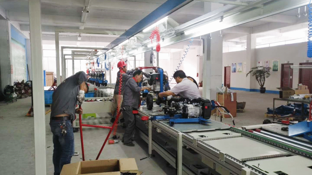
The assembly line adopts a strategy of “parallel assembly of engine and gearbox as dual cores, merging in final assembly”, typically using floor chains or slat conveyors.
Core Process Flow:
Component Sub-assembly → Gearbox Assembly (Core) → Engine Pre-assembly → Main Assembly Line Merge → Debugging & Testing → Painting & Final Inspection
Detailed Main Segments:
- Segment 1: Core Sub-assembly Lines
- Gearbox Assembly Line (Top Priority):
- Housing cleaning, leak testing.
- Sequential bearing press-fitting, installation of shafts, gears, differential assembly, gear shift fork mechanism.
- Key Processes: Gear backlash adjustment, differential/steering clutch calibration, housing sealing (application of sealant, tightening of high-strength bolts to specified torque and sequence).
- Fill with gear oil, perform no-load run-in test, check for smooth gear shifting and abnormal noise.
- Engine Sub-assembly: Installation of peripherals like air cleaner, muffler, starter pulley.
- Gearbox Assembly Line (Top Priority):
- Segment 2: Main Assembly Line
- Station 1: Main frame loading. Installation of engine mounts, gearbox mounts.
- Station 2: Engine-Gearbox Marriage. Align engine flywheel housing with gearbox input shaft, connect via flexible coupling or direct coupling, and secure fasteners. This is the first critical power transfer connection point.
- Station 3: Install main clutch, belt tensioner mechanism, or clutch linkage.
- Station 4: Install drive axle, final drive housing, rotary tine shaft assembly.
- Station 5: Install chain/gear drive case, connecting gearbox output to tine shaft input.
- Station 6: Install handlebar assembly, connect all control cables (clutch, throttle, steering clutch).
- Segment 3: Debugging, Testing & Painting
- Station 7: Static Debugging
- Adjust free play and end travel of all control linkages.
- Check all fasteners, especially those securing wheels and tines.
- Station 8: Dynamic Testing (Core)
- No-load Run Test: Start engine, test all forward gears, reverse, and neutral for clear, smooth operation.
- Steering Function Test: Operate steering clutch or differential lever, verify effective disengagement/engagement of drive wheels and flexible steering.
- Tine Shaft Rotation Test: Engage PTO, check for smooth tine shaft rotation and abnormal noise from chain/gear case.
- Clutch Test: Verify main clutch disengages completely and engages smoothly.
- Station 9: Load Test (Sampling)
- Apply simulated load to drive wheels and tine shaft using a dynamometer, testing engine power output, gearbox load capacity, and temperature rise.
- Station 10: Cleaning, touch-up painting, final inspection, labeling, packaging.
- Station 7: Static Debugging
III. Key Inspection Processes & Quality Control Points
- Gearbox Specialized Inspection
- Gear Contact Pattern Check: Use Prussian blue to inspect gear contact area and position, ensuring smooth transmission.
- Gearshift Force & Smoothness Test: Measure shift lever operation force with instruments to ensure it falls within standard range.
- Sealing Test: Perform pressure or fluorescent leak test on assembled gearbox housing.
- Critical Connection Point Inspection
- Engine-Gearbox Alignment: Check with dial indicator to prevent abnormal vibration and wear from misalignment.
- High-Strength Bolt Torque Verification: 100% torque-controlled tightening of housing bolts, wheel bolts, and tine bolts with traceable data.
- Safety & Performance Testing
- Guard Safety Distance Check: Ensure all guards for rotating parts (belts, chains, tine shaft) comply with safety standards.
- Emission & Noise Testing (as per regulations).
- Tine Dynamic Balance Test (for high-speed tines): Prevents severe vibration.
Part II: Power Tiller Assembly Line (Overall Description of Linear Differential Chain-Drive Conveyor)
I. Production Line Design Positioning
This production line adopts a unidirectional linear flow layout specifically designed for the large-scale standardized production of differential chain-drive power tillers. Characterized by sequential processes and controllable production takt time, this layout is suitable for mass manufacturing scenarios with an annual output exceeding tens of thousands of units.
II. Production Line Process Characteristics
- Rigid Process Design
Production is organized according to the fixed sequence of “frame → transmission → final assembly → testing,” ensuring a stable takt time of 3–5 minutes(or as customized) per unit. Balanced operation time across processes enables a unidirectional linear flow of logistics. - Dual Mainline Parallel Operations
A dedicated gearbox assembly line and a main host assembly line are established, with precision docking at the integration station. Key transmission components adopt a modular pre-assembly approach to enhance final assembly line efficiency. - Heavy-Duty Process Design
Equipped with specialized hoisting equipment and heavy-duty positioning tooling to meet the precise assembly requirements of large-mass power tiller components. Critical connection points utilize torque-controlled fastening systems to ensure structural reliability.
III. Quality Control System
- In-Process Quality Monitoring
Quality gates are set at critical stations such as gearbox housing assembly, differential assembly, and powertrain integration, employing professional equipment like coordinate measuring machines and gear meshing detection for in-process inspections. - Online Testing System
A comprehensive test station is installed at the end of the line, including load testing, steering testing, and PTO function testing. Test data is uploaded in real-time to the MES system, establishing a complete quality traceability record.
IV. Production Line Technical Configuration
- Conveyor System: Utilizes heavy-duty roller conveyors with a load capacity of 500 kg per station, equipped with precision positioning devices.
- Material Supply: Implements a Set Parts Supply (SPS) system, with key components delivered just-in-time.
- Information System: Integrates an MES production management platform for real-time monitoring of production progress, quality data, and equipment status.
V. Capacity and Flexibility Analysis
- Standard Capacity: Achieves an annual output of the customized capacity per shift, with overall equipment effectiveness (OEE) ≥ 85%.
- Product Adaptability: Suitable for mixed-flow production of 3–5 power variants within the same platform.
- Scalability: Capacity can be increased by 30–50% by adding parallel workstations.
VI. Key Advantages
- High Efficiency: Process balance rate ≥ 90%, with work-in-progress (WIP) reduced by 40%.
- Easy Management: The linear layout simplifies on-site management and material delivery routes.
Through its design philosophy of process specialization, in-process quality control, and digitalized management, this production line enables the transition of power tiller assembly from discrete manufacturing to flow production, significantly improving manufacturing efficiency while ensuring product reliability.
We can customize according to the client’s product specifications, production capacity or other requirements.
We provide comprehensive services including design, production, and installation/commissioning.