Household Heater Assembly Line—Oil-filled Radiator Heaters Assembly Line—Heater Production Line
Oil-filled radiator heaters consist of three main systems: the thermal core, electrical control, and outer casing, operating on the principle of sealed oil-circulation heat dissipation. The core of production lies in ensuring absolute sealing integrity and electrical safety, following an inside-out assembly process where the key step is the fully automated sequence of vacuum evacuation, precise oil injection, and high-temperature sealing. Multi-level testing is integrated throughout, including leak detection, inline electrical safety tests, and simulated operational aging tests, with optional MES system integration for full data traceability. Modern assembly lines employ differential chain conveyor systems to enable flexible stopping and precise positioning of workpiece pallets, supporting mixed-model production, and can optionally integrate RFID tracking, intelligent fastening, and visual error-proofing technologies. This system, through precise structural design, strict process control, and intelligent production line integration, ensures high product safety and reliability while significantly enhancing production flexibility, efficiency, and quality controllability.
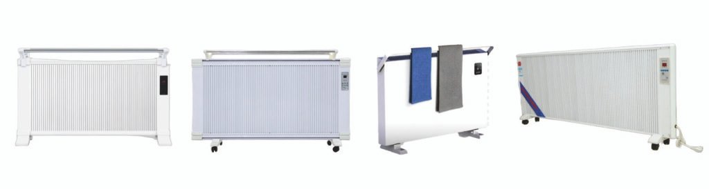
Heater Assembly Lines are suitable to Produce heaters. (If clients have more requirements or want to produce the other heaters, welcome to contact us.)
Part I: Structure of Oil-Filled Radiator Heaters
The structure of an oil-filled radiator can be divided into three main systems, centered around a sealed oil-circulation heat dissipation system.
1. Thermal Core System
- Fin Stack: Multiple hollow steel fins welded together to form internal interconnected oil channels and external heat-dissipating surfaces.
- Thermal Oil: A special modified mineral oil sealed within the fin cavities, serving as the heat storage and transfer medium. It lasts the lifetime of the heater and does not require replacement.
- Heating Element: Installed at the bottom of the fin stack, immersed directly in the thermal oil, acting as the heat source.
2. Electrical Control System
- Thermostat: The core control component. It senses oil or ambient temperature and automatically cycles power to maintain the set temperature.
- Overheat Protector: An independent safety redundancy device. It permanently cuts power if the thermostat fails and abnormal overheating occurs.
- Tip-Over Switch: Automatically cuts power if the unit is tilted beyond a safe angle.
- Power Switch/Adjustment Knob: Used for turning the unit on/off and adjusting power levels.
3. Mechanical & Casing System
- Casing: Includes the base plate, side decorative panels, top cover, and protective rear grille. Provides support, protection, and aesthetic appeal.
- Drying Rack: A foldable rack on top for drying small items of laundry.
- Swivel Casters: Four casters mounted at the bottom for easy mobility.
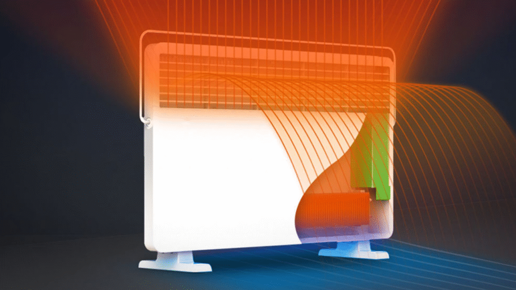
Working Principle: The heating element warms the thermal oil at the bottom → The hot oil rises, transferring heat to all fins → The fins dissipate heat into the room via thermal radiation and natural air convection → The cooled oil sinks back to the bottom to be reheated, creating a continuous cycle.
Part II: Assembly/Testing Processes of Oil-Filled Radiator Heaters
The core objectives of the assembly and testing processes are to ensure absolute sealing integrity and 100% electrical safety.
Assembly Process Flow
Follows an inside-out, core-first principle.
- Core Module Preparation:
- Fin Stack Welding: A high-frequency welder joins individual fins into a stack.
- Install Heat Source & Process Port: The heating element and the process port (for vacuum/oil filling) are welded to the bottom of the cavity.
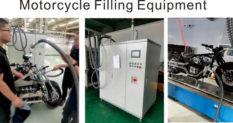
- Core Sealing Process (Most Critical Step):
- This step is performed on a fully automated specialized machine.
- Sequence: Clamp the process port → Evacuate to a high vacuum → Inject a precise quantity of thermal oil → High-temperature melt-seal the process port, creating a permanently sealed oil circuit core. Vacuum level and oil volume are precisely controlled by the machine.
- Final Assembly Integration:
- Mount the sealed core onto the base plate and support frame.
- Assemble the casters, electrical components (thermostat, wiring harness, protectors), casing, and drying rack.
Testing Process System
Testing acts as a “safety net” throughout production.
- In-Process Testing (Prevents Defect Flow):
- Post-Weld Seal Pre-check: Before oil filling, perform an initial pressure hold or water immersion leak test on the welded cavity.
- Post-Sealing High-Precision Leak Test: After sealing, use equipment like a helium mass spectrometer for micro-leak detection.
- Inline Safety Testing (100% Mandatory Full Inspection):
- After final assembly, every single unit must pass Dielectric Strength (Withstand Voltage) Test and Ground Continuity Resistance Test in sequence. Non-compliant units are automatically locked out.
- Final Aging & Functional Testing (Performance Verification):
- Units enter an aging test chamber and operate at full rated power for 30+ minutes.
- Purposes:
- Verify functions like heating up, temperature regulation, and auto-shutoff.
- Activate and test the overheat protector for correct operation.
- Perform tip-over protection test.
- Expose potential early-life defects through thermal stress (“burn-in”).
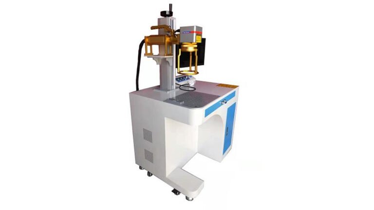
- Final Inspection & Traceability:
- Re-test key safety items and conduct a final visual inspection.
- Apply labels and markings. All key component data and test results are linked to the product serial number via a MES (Manufacturing Execution System), enabling full traceability.

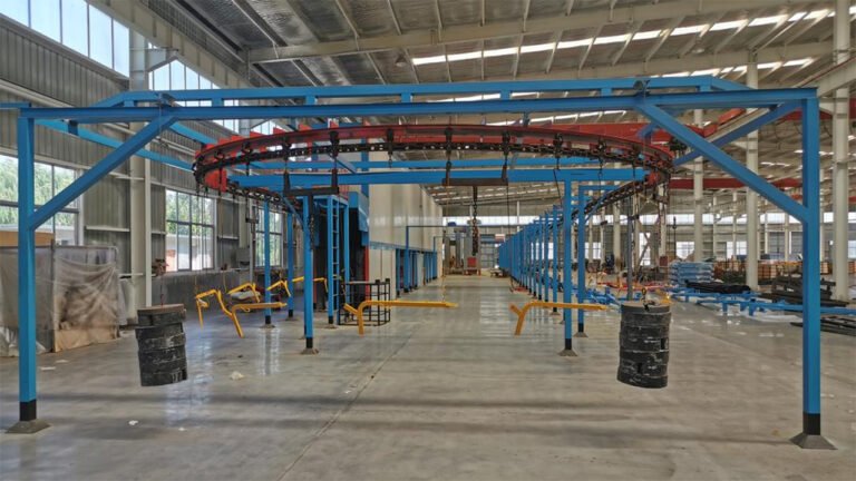
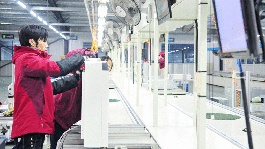
Part III: Oil-Filled Radiator Heaters Assembly Line
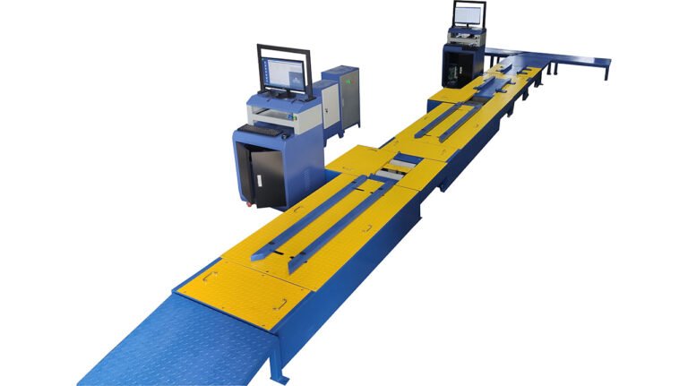
The Differential Chain Assembly Line is an efficient and flexible conveying system used in the production of oil-filled radiator heaters. Its core feature lies in utilizing the dual-chain differential principle to achieve precise stopping and smooth transfer of workpiece pallets at assembly stations, making it particularly suitable for the multi-process, rhythm-adjustable assembly requirements of oil-filled radiators.
I. Core Characteristics of the Differential Chain System
Working Principle
- Employs two parallel conveyor chains that generate speed differences at specific stations through independent drives
- Workpiece pallets advance when the chains move synchronously and stop precisely when a speed differential occurs
- Stop duration at each station is flexibly adjusted via PLC programming
Main Advantages
- Flexible Production: Supports mixed-model production lines, allowing stations to operate independently
- Precise Positioning: Workpiece pallets stop stably with positioning accuracy up to ±1mm
- Automatic Flow: Products are conveyed automatically, reducing worker labor intensity
- Intelligent Accumulation: Automatically buffers when upstream congestion occurs, preventing line blockage
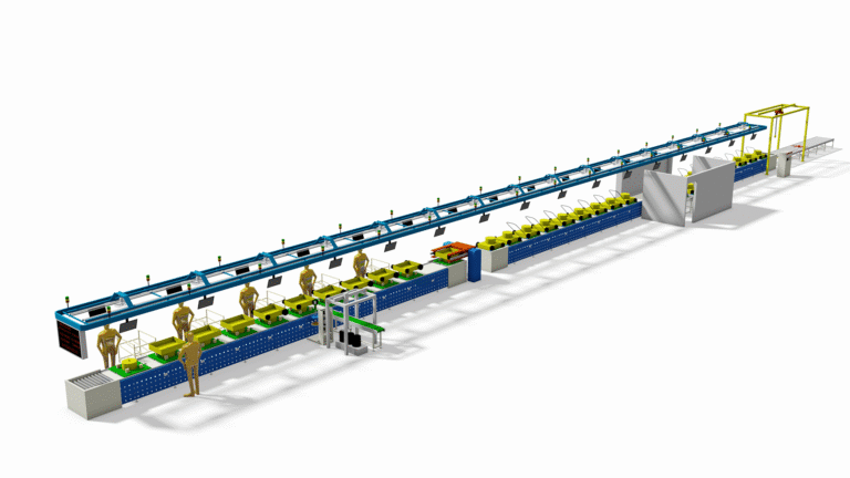
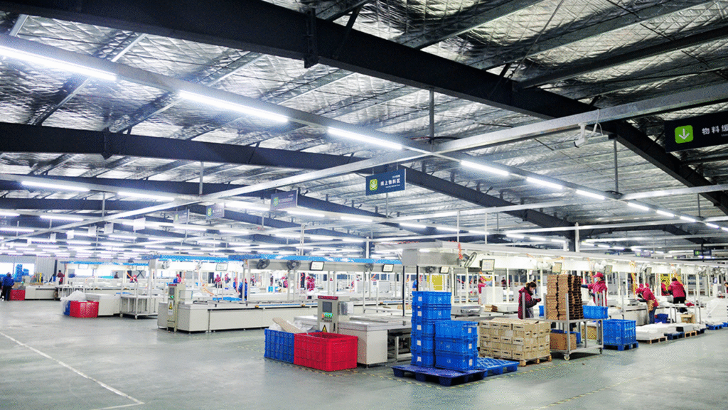
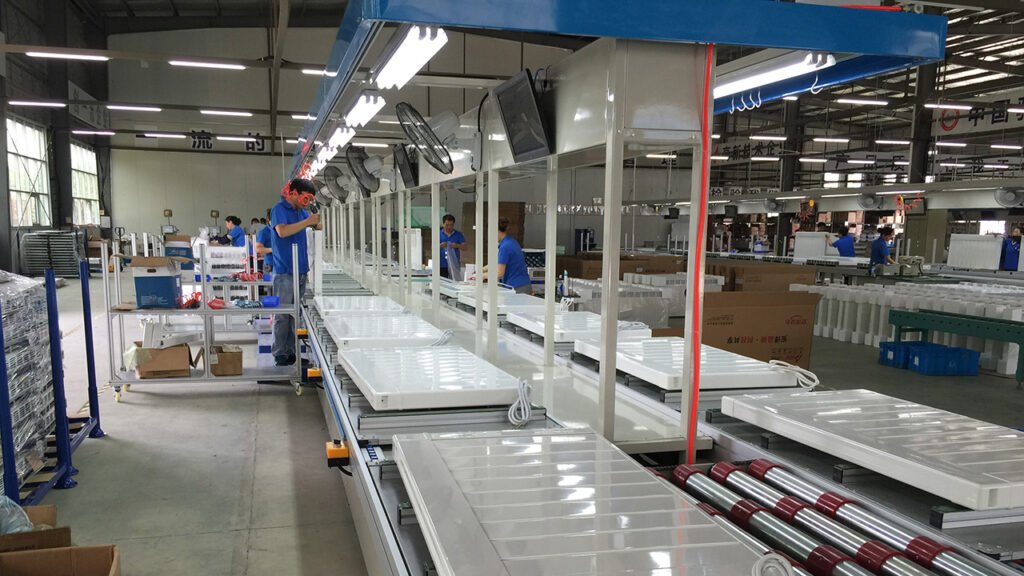
II. Typical Layout of the Assembly Line
The assembly line adopts a rectangular or U-shaped closed-loop layout, comprising the following zones:
Loading and Core Sealing Zone
- Completes core processes such as fin stack welding, vacuum evacuation, and oil filling
- Functions as an independent workstation, with finished core modules fed into the main line via a lift
Differential Chain Main Assembly Line
Equipped with 15-25 assembly stations along the line, typical sequence includes:
- Installing the base plate, securing the core module, assembling casters
- Installing the thermostat, wiring, and control board
- Key Test Point: Inline withstand voltage test (1500V/60 seconds)
- Installing outer casing, drying rack, and other components
- Final fastening and preliminary inspection
Aging Test Zone
- Transferred via a transfer machine to a multi-layer circulating aging line
- Undergoes 40-60 minutes of powered full-functional testing
Unloading and Packaging Zone
- Qualified products are automatically unloaded for labeling and packaging
- Non-conforming products are diverted to a rework line
III. Key Technology Integration
Information Management
- RFID chips embedded in workpiece pallets enable single-piece flow traceability
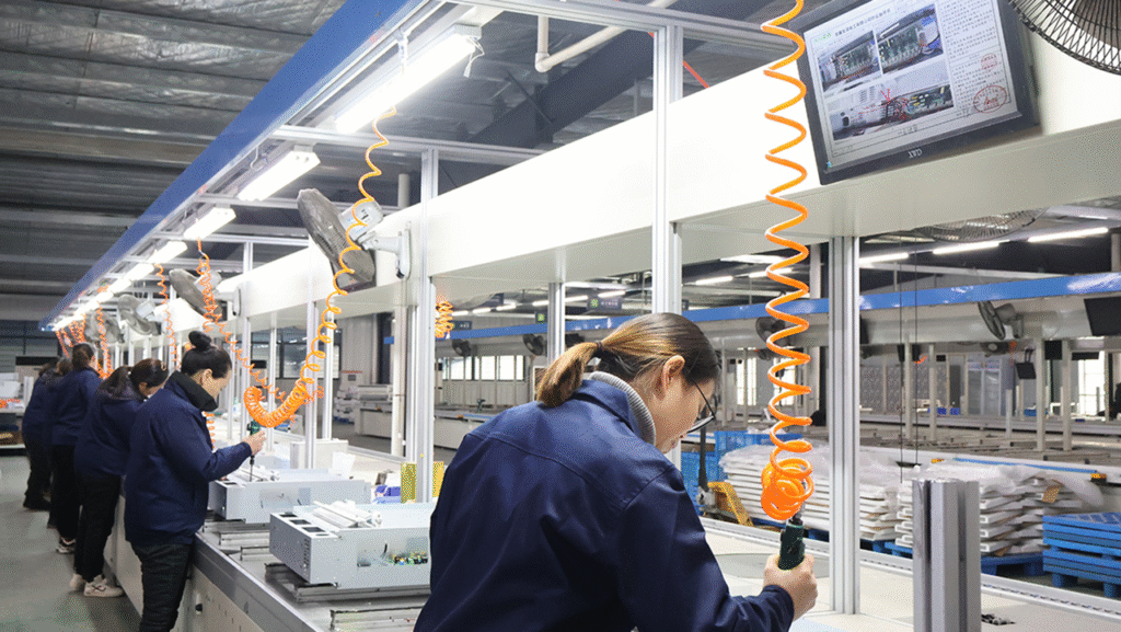
Intelligent Assembly
- Critical stations equipped with servo-electric screwdrivers, with data uploaded in real-time
- Industrial camera vision systems automatically verify installation status
Real-Time Monitoring
- Equipped with energy consumption monitoring modules and efficiency dashboards
- Real-time display of production data: output, downtime, yield rate, etc.
IV. Typical Line Parameters
- Line Length: 40-80 meters (U-shaped layout saves space)
- Number of Stations: 15-30 (configured based on process complexity)
- Cycle Time: 40-90 seconds per unit (stop duration adjustable)
- Conveyor Speed: 0.5-5 meters per minute (variable frequency drive)
- Positioning Accuracy: ±1-2 millimeters (meets automation requirements)
- Load Capacity: 50-100 kilograms per workpiece pallet
V. Summary of Application Value
The differential chain assembly line addresses the rigidity limitations of traditional conveyor lines through its unique differential stopping mechanism, achieving three major improvements:
Enhanced Flexibility
Rapid model changeover capability adapts to small-batch, multi-variant order requirements
Intelligent Upgrade
Integration of data traceability, inline inspection, and error-proofing systems ensures consistent product quality
Efficiency Optimization
Reduces inter-process waiting time, balances production rhythm, and improves overall efficiency
This assembly line has become the standard configuration in modern oil-filled radiator heater factories. While ensuring high product safety and reliability, it significantly enhances manufacturing competitiveness.
We can customize according to the client’s product specifications, production capacity or other requirements.
We provide comprehensive services including design, production, and installation/commissioning.