
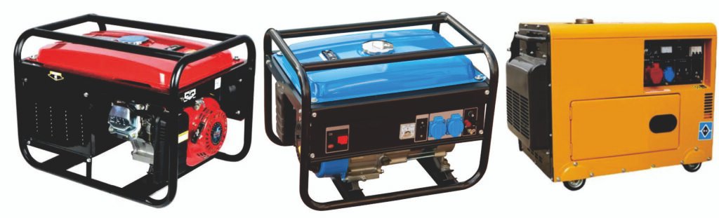
This paper introduces household generators (gasoline/diesel/portable/fixed types) covering four core parts: their structure is composed of power, generation, voltage regulation and auxiliary systems, with internal combustion engines as main power and stator-rotor as generation core; assembly follows part inspection, winding, power system fitting, component installation in order; testing includes pre-preparation, no-load preheating, step-by-step loading, rated load running and shutdown procedures.
It also details the generator’s assembly line, including several core workstations from pre-inspection to load testing, supporting lightweight equipment, and its features of manual-assembly dominated, scalable, closed-loop detection and compact layout.
Generator Assembly Lines are suitable to Assemble/Produce generators. (If clients have more requirements or want to produce the other generators, welcome to contact us.)
Part I. Structure, Assembly and Testing Processes of Household Generators
Household generators are usually composed of a power system, a power generation system, a voltage regulation system, etc. Below is an introduction to their structure, assembly and testing processes:
Structure of Household Generators
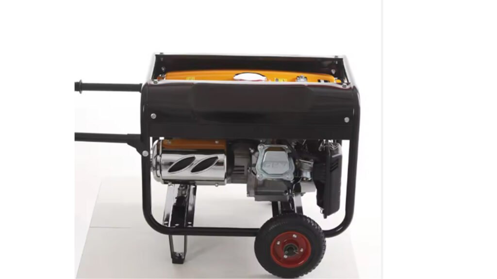
- Power system: Internal combustion engines are the most common type. Taking gasoline generators as an example, they convert the chemical energy of fuel into the mechanical energy of the piston’s reciprocating motion through a four-stroke operating cycle (intake, compression, power, exhaust). In addition, there are new energy power units such as solar photovoltaic panels and wind turbine blades, which convert solar energy and wind energy into mechanical energy respectively.
- Power generation system: It mainly consists of a stator and a rotor. The stator is a fixed winding made of silicon steel sheets and enameled copper wires, used for inducing electric current. The rotor generates a rotating magnetic field—permanent magnet rotors are mostly adopted in small generators, while excitation winding rotors are commonly used in high-power generators.
- Voltage regulation system: Generally composed of a voltage regulator such as an AVR (Automatic Voltage Regulator). By detecting the output voltage and feeding it back to the excitation winding to adjust the current, it stabilizes the magnetic field intensity and ensures a constant output voltage.
- Other auxiliary systems: Including the fuel system (consisting of a fuel tank, carburetor/fuel injector, fuel pump, etc.) for fuel storage and supply; the cooling and exhaust system (consisting of coolant, fan, muffler, etc.) for preventing engine overheating and reducing noise; and the control system (including a control panel with power outlets, circuit breakers, monitoring displays, etc.) for monitoring and controlling the generator’s operation.
Assembly Process of Household Generators
- Inspection and cleaning of parts: Check if the stator, rotor, casing, end cover and other parts are damaged or deformed in appearance; blow off surface dust, iron filings and other impurities with compressed air. Inspect the insulation of windings for good condition and verify that the number of coil turns meets the requirements.
- Winding and coil embedding: Wind electromagnetic wires on a winding mold with uniform tension and neat arrangement. Then embed the wound coils into the stator slots. During embedding, protect the wire insulation to avoid scratching the slot paper, and drive in slot wedges to fix the coils after embedding.
- Installation of the power system: Taking gasoline generators as an example, first install the crankshaft and apply engine oil to the bearings, then install the connecting rod, piston assembly, connecting rod cover and other components in sequence, paying attention to the installation direction of each part and the bolt tightening torque. Next, install the camshaft, timing gear chamber cover, cylinder head assembly and other parts.
- Installation of other components: Install the cooling fan, flywheel, ignition coil, carburetor, exhaust pipe and other components, and connect the fuel pipelines, wires and other accessories properly.
Testing Process of Household Generators
- Pre-test preparation: Inspect the generator for appearance damage and firmness of connection parts; check that the liquid levels of coolant, engine oil and fuel are normal and the quality is up to standard. Prepare suitable load equipment (e.g., light bulbs, electric heaters) and testing tools (e.g., multimeters, thermometers, tachometers).
- Start-up and preheating: Start the generator in accordance with the start-up instructions, and let it run idly for preheating for 3-5 minutes after start-up. Observe if the engine sound and exhaust condition are normal, and if the parameters such as voltage and frequency displayed on the instrument are within the specified range.
- Step-by-step load application: Start with a small load, observe the changes in the generator’s operating parameters (e.g., voltage, current, rotational speed) after each load application to ensure stable operation. Gradually increase the load to the rated power and continuously monitor all parameters during the loading process.
- Rated load operation test: Run the generator at the rated power for 1-2 hours, record data such as voltage, current, frequency and temperature every 15-30 minutes, and observe the generator’s operation stability, heat dissipation and vibration.
- Load unloading and shutdown: After the test, unload the load step by step, then let the generator run idly for another 3-5 minutes. After the engine temperature drops, shut down the generator in accordance with the shutdown instructions.
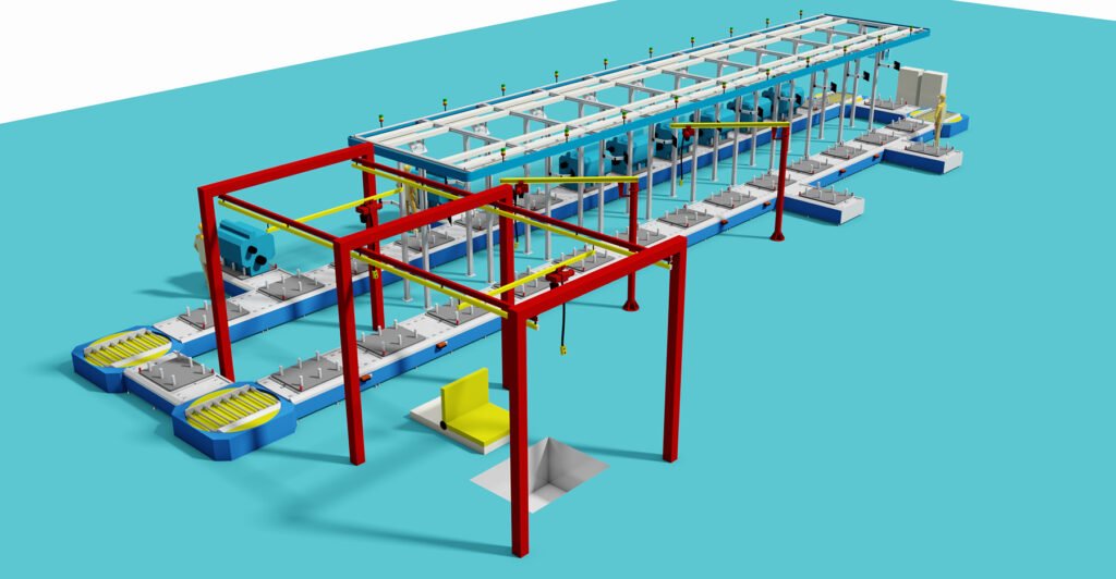
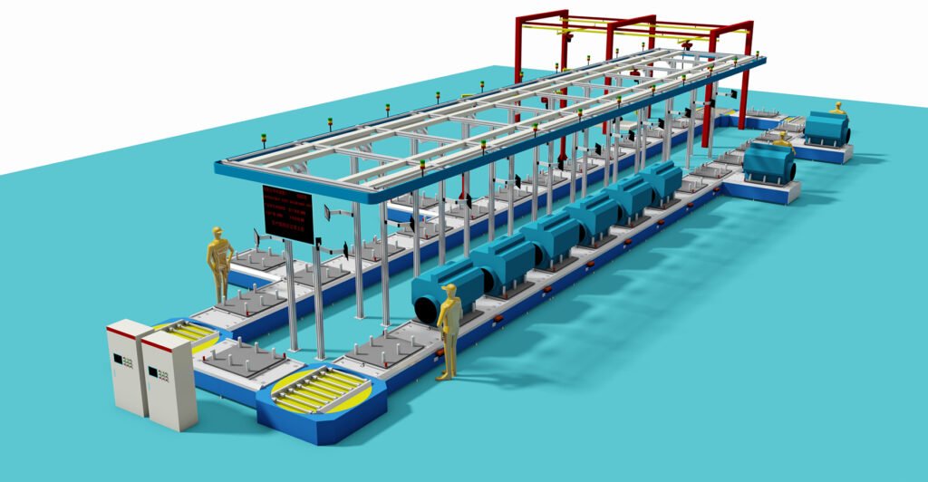
Part II. Assembly Line for Household Generators
(Mainly for gasoline/diesel models, compatible with small portable/household fixed models)
The assembly line for household generators features a flow-line workstation layout combined with manual assembly and dedicated tooling assistance, adapted for small-batch and multi-specification production. It corely follows the assembly logic of from inside to outside, from mechanical to electrical components, and from sub-assemblies to complete machine assembly. Below is the detailed introduction of workstation layout, core equipment, assembly process and the way to obtain white-background/structural schematic diagrams of the assembly line, along with the description of supporting real-scene references.
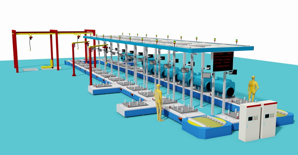
I. Core Workstation Layout of Household Generator Assembly Line (Single Line, in Process Order)
Pre-Area: Parts Material Preparation and Pre-Inspection
- Function: Sort generator loose parts (engine cylinder block, stator/rotor, casing, circuits, hardware, etc.) by workstation, and complete insulation testing, dimensional recheck, cleaning and chip removal (e.g., stator winding continuity test, bolt thread cleaning).
- Equipment: Compressed air gun, multimeter, micrometer, parts rack.
Workstation 1: Core Engine Assembly
- Process: Cylinder block fixing → Crankshaft/connecting rod/piston assembly → Camshaft + timing gear installation → Cylinder head/valve assembly fitting. Tighten bolts according to torque requirements throughout the process, and apply special lubricating oil to bearing positions.
- Tooling: Engine assembly fixture, digital torque wrench, small press machine (for pressing bearings/bushings).
Workstation 2: Power Generation System Assembly (Stator/Rotor Fitting)
- Process: Fix the stator inside the casing → Connect the rotor with the engine crankshaft coaxially → Detect the stator-rotor gap (to avoid friction) → Install the end cover with sealing, completing the mechanical fixation of the power generation core.
- Tooling: Stator-rotor centering fixture, feeler gauge, sealant dispensing machine.
Workstation 3: Auxiliary System Assembly (Cooling/Fuel/Exhaust)
- Process: Install cooling fan/wind guide cover → Connect fuel tank/carburetor/fuel pipeline → Assemble exhaust pipe + muffler → Install oil pot + oil pipeline, ensuring no leakage and regular pipeline routing.
- Key Points: Fuel/oil pipelines shall be fixed against loosening, and the muffler gasket shall be attached in place.
Workstation 4: Electrical System Assembly and Wiring
- Process: Install AVR (Automatic Voltage Regulator) → Wire ignition coil/spark plug → Assemble control panel (socket/circuit breaker/instrument) → Arrange circuits (fix with cable ties) → Connect grounding terminal, completing the electrical circuit of the whole machine.
- Equipment: Wire stripper, crimping pliers, wire harness fixing tooling. Conduct core tests of circuit continuity and insulation resistance (≥500MΩ).
Workstation 5: Complete Machine Assembly and Exterior Fitting
- Process: Install engine guard/whole machine casing → Assemble armrest/caster (portable model) → Install fuel filler cap/oil filler cap cover → Attach labels (nameplate/operation mark). Check the fitting degree of the casing and no collision gaps.
Workstation 6: No-Load Initial Test (On-Line Detection)
- Process: Fill test fuel/oil → Start the generator → Run idly for 3-5 minutes → Detect voltage/frequency, engine speed, exhaust/abnormal noise, and eliminate obvious faults (e.g., unstable idling, voltage drift).
- Equipment: Portable dynamometer, voltage/frequency meter, tachometer.
Workstation 7: Load Test and Performance Calibration
- Process: Connect analog load (resistance box/load cabinet) → Gradually apply load to rated power → Calibrate AVR parameters (to stabilize output voltage) → Detect temperature rise/vibration/noise and record test data.
- Core Standard: Under rated load, the voltage fluctuation is ≤±2%, frequency fluctuation ≤±1Hz, without oil leakage/electric leakage/abnormal vibration.
Post-Area: Finished Product Finishing and Packaging
- Process: Drain the test fuel/oil after passing the test → Clean the surface of the whole machine → Attach qualified marks → Cover with protective film/put into carton → Assemble and pack accessories (instruction manual, tools, oil pipe) together.
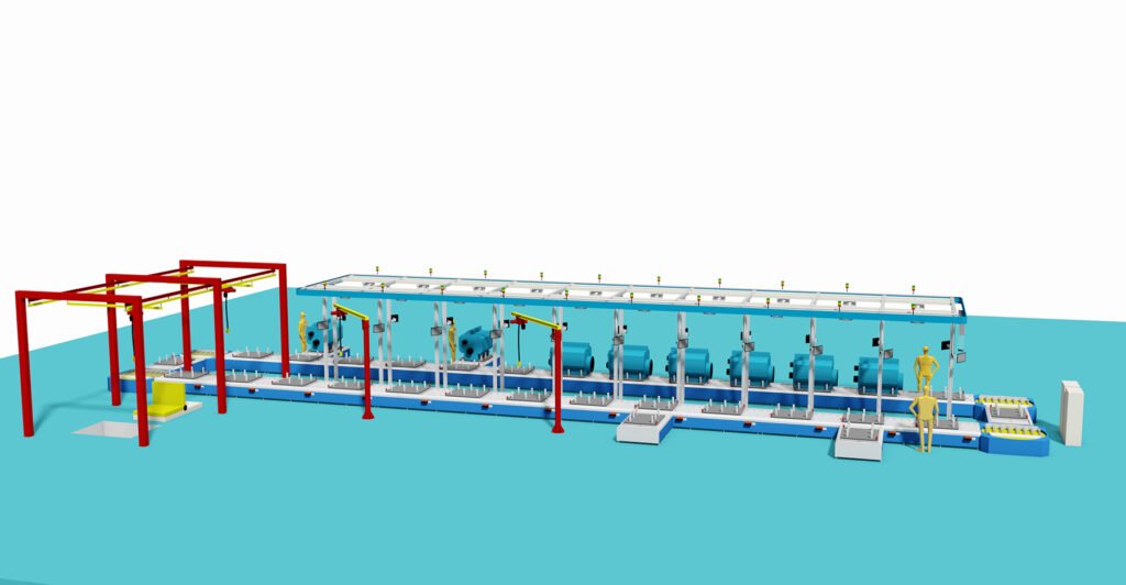
II. Core Supporting Equipment of the Assembly Line (Lightweight for Household Models, No Large-Scale Automatic Equipment)
- Tooling Fixtures: Engine positioning fixture, stator-rotor centering fixture, complete machine test fixing table (to prevent displacement during testing);
- Testing Tools: Digital torque wrench, multimeter, insulation resistance tester, integrated voltage/frequency/speed detector;
- Auxiliary Equipment: Compressed air gun (for cleaning), dispensing machine (for sealant/threadlocker), load cabinet (for analog load testing), forklift/trolley (for inter-workstation transfer);
- Safety Equipment: Workstation fume hood (for engine commissioning), insulation mat, emergency stop button.
III. Core Characteristics of Household Generator Assembly Line
- Lightweight: Dominated by manual assembly, with only core processes equipped with dedicated tooling, adapted to the small size and multi-specification characteristics of household generators (power ≤10kW);
- Scalability: Quick switch between portable and fixed models by replacing workstation fixtures without reconstructing the production line;
- Closed-Loop Detection: 100% full inspection for key processes (electrical wiring, no-load/load testing) to prevent non-conforming products from flowing into subsequent processes;
- Compactness: The single line is about 15-20 meters in total length with small floor space, suitable for small and medium-sized manufacturing enterprises. The distance between workstations is 0.8-1.2 meters, conforming to the manual operation moving line.
We can customize according to the client’s product specifications, production capacity or other requirements.
We provide comprehensive services including design, production, and installation/commissioning.