
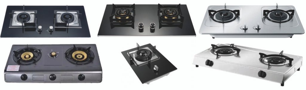
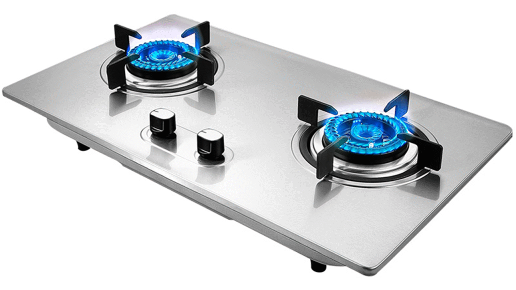
Gas Stove Assembly Lines are suitable to Assemble/Produce Gas Stoves. (If clients have more requirements or want to produce the other Gas Stoves, welcome to contact us.)
Part I. Gas Stove Structure, Key Assembly and Testing Process
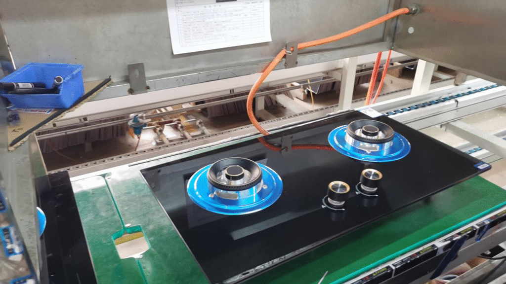
I. Structure of Gas Stove (typically composed of four main systems:)
- Gas Supply and Control System: Controls the gas flow and shut-off, including the inlet pipe, valve body, knob, and ignition device.
- Combustion System: The core is the burner (consisting of the injector and fire cap), which mixes gas with air and ensures stable combustion.
- Safety System: The core is the flame failure protection device (thermocouple or ion-sensing type). It automatically cuts off the gas supply in case of accidental flame extinguishment, as required by national mandatory safety standards.
- Exterior and Auxiliary Systems: Include the stove surface, pot supports, drip tray, battery compartment, etc.
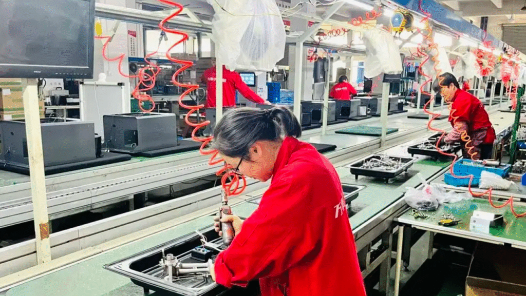
II. Assembly Process (Modular Line)
- Base & Gas Module
- Install pipes & valves → pressure test
- Panel & Controls
- Mount surface → install knobs/ignition/flame-failure device
- Burner System
- Place burners → add caps & drip trays
- Final Assembly
- Combine modules → fasten → attach labels
III. Three-Stage Testing
1. Online Testing (Every Unit)
- Leak Test: 0.6kPa, 1 min hold (≤5% drop)
- Ignition: 5 tries, 100% success, ≤3 sec
- Flame-Failure Cutoff: ≤60 sec (thermocouple) / ≤5 sec (ion)
- Flame Check: Blue, uniform, stable
2. Full Inspection (100%)
- Visual check (no damage, complete parts)
- Full function test (ignition/adjustment/safety)
- Electrical safety (insulation ≥10MΩ)
- Pre-pack verification (model/gas type labels)
3. Sampling Tests (Per Batch)
- Leak: 4.2kPa, no leakage
- Heat Input: Within ±10% of rating
- Efficiency: ≥63% for Grade 1
- CO Emissions: ≤0.05%
- Durability: 6,000 knob cycles
IV. Key Controls
- Sealing: Torque wrenches + sealants
- Burner Precision: Fire cap holes ±0.1mm
- Safety Device: Thermocouple 3–5mm from flame
- Cleanliness: Air-blow pipes before assembly
Part II. Differential Chain Assembly Line for Gas Stove
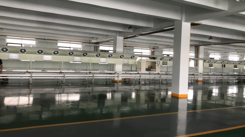
1. Line Overview
The differential chain assembly line is a mainstream conveying system for gas stove production. By utilizing variable-speed chains and stoppers, it enables non-synchronous movement between workstations, balancing the efficiency of a flow line with the flexibility of a cell line.
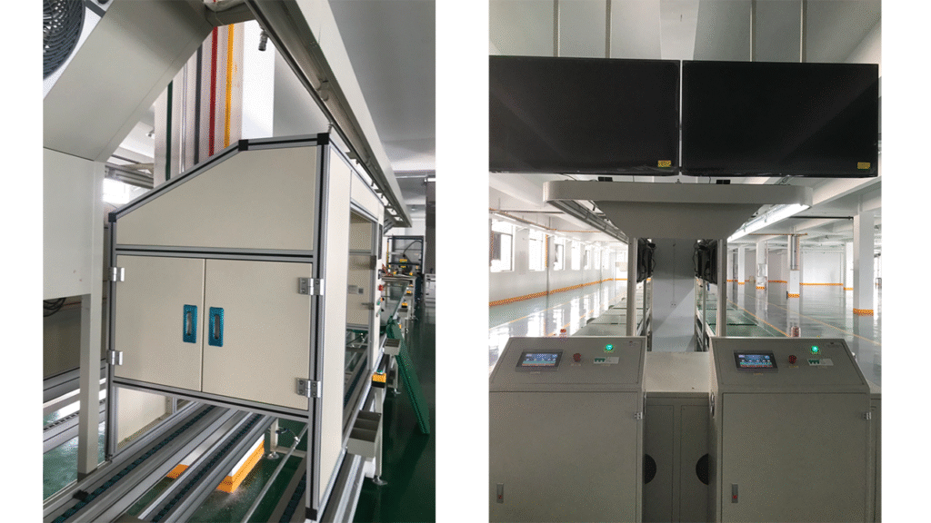
2. Core Structure
Conveyance System: Includes dual-speed chains, variable-frequency motor drives, workstation stoppers, and a return feeding mechanism.
Workstation Modules: Comprise assembly workstations, integrated testing islands, and lifting/rotating platforms for bottom assembly.
Control System: Centered on a PLC, equipped with a human-machine interface (HMI) and an ANDON light system.
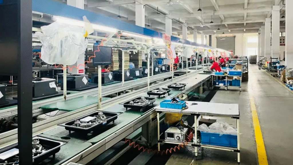
3. Typical Process Layout
A linear differential chain layout typically includes the following stations in sequence: feeding, valve assembly, pipeline connection, airtightness pre-check, panel assembly, burner installation, online testing island, final inspection, packaging, and offloading. Key workstations are equipped with positioning stoppers.
- Workstation Spacing: 2.2–2.5 meters
- Line Speed: 0.8–1.5 meters/minute (adjustable)
- Load Capacity: Maximum 50 kg per pallet
4. Differential Operation Principle
The system operates in three states:
Conveyance Phase: Chains run quickly (3–5 m/min), pallets flow freely, cycle time is 30–45 seconds.
Assembly Phase: Chains slow or stop, stoppers rise to secure pallets, operation time is 60–180 seconds.
Testing Phase: Chains stop, automated testing and manual monitoring occur, testing time is 45–60 seconds.
Key Mechanisms: Accumulation function (pallets can be temporarily stored if downstream stations are busy), variable cycle times (different processes can have different operation times), and empty station bypass (pallets quickly pass through idle stations).
5. Assembly Process Breakdown
Gas Circuit Module Section (Stations 1–4):
- Station 1: Baseplate positioning and installation of valve assembly, torque controlled at 3.5±0.2 N·m.
- Station 2: Connection of gas distribution pipes and installation of joints, with sealant applied.
- Station 3: Pre-tightening inspection and bracket installation.
- Station 4: Airtightness pre-check using 0.4 MPa nitrogen pressure held for 30 seconds, allowable pressure drop ≤1%.
Panel Module Section (Stations 5–8):
- Station 5: Panel cleaning and positioning via vacuum adsorption.
- Station 6: Installation of knob assembly and connection of micro-switches.
- Station 7: Installation of igniter and flame failure protection probe, with probe spacing adjusted to 3.5±0.5 mm.
- Station 8: Circuit connection and preliminary functional inspection.
Final Assembly and Testing Section (Stations 9–12):
- Station 9: Integration of gas circuit and panel modules, with automatic tightening of 8 fastening points.
- Station 10: Burner installation and placement of fire caps.
- Station 11: Online integrated testing station.
- Station 12: Visual inspection, labeling, and release to the packaging section.
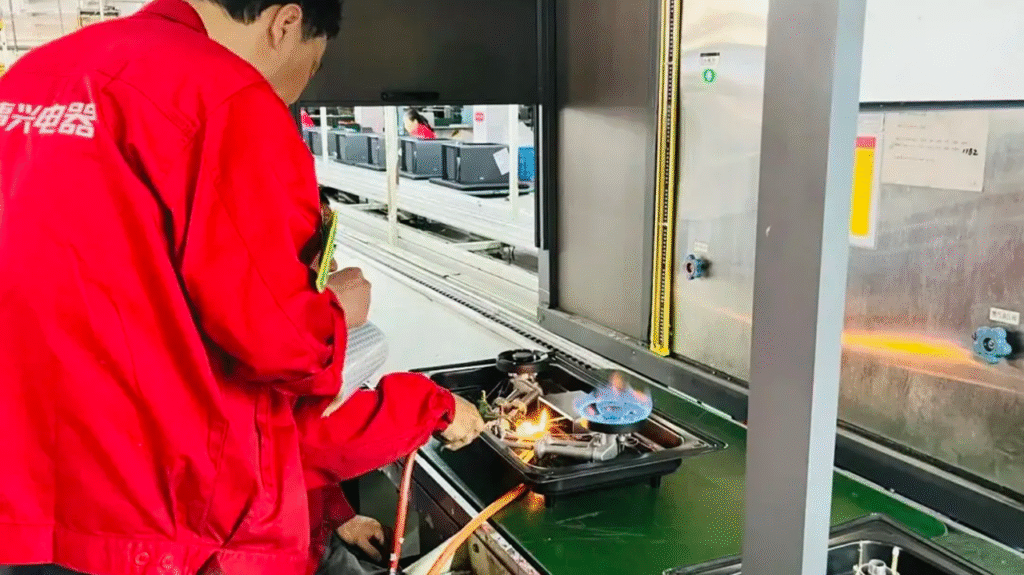
6. Online Testing
The integrated testing station (Station 11) includes automatic docking mechanisms (quick-connect gas couplings and electrical contacts) and executes a fully automated test sequence.
Test Sequence:
- Phase 1: Airtightness test
- Phase 2: Ignition cycle test
- Phase 3: Flame failure protection response test
- Phase 4: Leak re-check using methane sensors (≤50 ppm)
All test data is uploaded to the MES, and non-conforming products are automatically marked and diverted.
7. Advantages
Compared to Synchronous Flow Lines:
- Higher flexibility (independent workstation operations)
- Better fault tolerance (localized stoppages do not affect the entire line)
- Lower investment (over 40% cost savings compared to fully automated lines)
Compared to Manual Cell Lines:
- Higher efficiency (automatic material flow reduces handling)
- More consistent quality (real-time monitoring via integrated online testing)
- Reduced labor intensity (ergonomic design)
8. Application Recommendations
Suitable Scenarios:
- Medium-scale factories with annual production capacity of 150,000–300,000 units
- Production requiring multiple product models (5–10 series)
- Frequent switching between gas types (e.g., natural gas/LPG)
Selection Points:
- Chain Type: Recommended engineered plastic differential chain (noise <65 dB)
- Testing Integration: At least dual-station testing for airtightness and ignition
- Traceability System: RFID-equipped pallets bound to product serial numbers
- Expansion Reserve: Approximately 20% additional workstation space reserved for future upgrades
We can customize according to the client’s product specifications, production capacity or other requirements.
We provide comprehensive services including design, production, and installation/commissioning.