
Designed for the large-scale production of electric tools, this assembly line consists of conveying, tooling, workstation, control and auxiliary systems. It leverages the differential chain to enable 2-3x speed conveyance of tooling plates, realizing a closed-loop operation from workpiece loading, differential conveying and station assembly to testing, aging and packaging. The PLC controller collaborates with sensors for precise speed and position control, adapts to the production of multiple tool types, and features flexible speed regulation, efficient assembly and quality traceability, serving as core equipment for the standardized production of electric tools.
Electric Tools Assembly Lines are suitable to Assemble/Produce Electric Tools. (If clients have more requirements or want to produce the other Electric Tools, welcome to contact us.)
Part I. Electric Tools
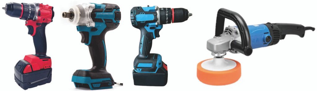
Electric tools are working equipment that uses electric power as the power source, driven by electric motors or electromagnets, converting electrical energy into mechanical energy. Here are some common types of electric tools:
Drilling/Fastening Tools
- Electric drill: The most common electric tool, mainly for drilling holes in metal, wood, plastic and other materials. Some models can be fitted with screwdriver bits for tightening/loosening screws.
- Impact drill: Combines drilling and impact functions, capable of drilling holes in hard materials such as concrete and brick walls.
- Electric wrench: Primarily for installing and removing threaded fasteners. With its high torque, it can easily tighten or loosen large bolts, widely used in auto repair, steel structure and other fields.
Sanding/Polishing Tools
- Sander: Includes orbital sanders, sheet sanders, detail sanders and other types, mainly for fine sanding of woodworking surfaces, scratch-free polishing, and sanding of edges, corners and curved surfaces.
- Polisher: Commonly used for mirror polishing of car paint and metal surfaces to restore a like-new shine.
Woodworking-Specific Tools
- Router: Also called a carving machine, used for grooving, edge trimming, pattern carving and other operations on wood, meeting the fine processing needs of woodworking in decoration, furniture making and other aspects.
- Electric planer: For planing wood or wood structural parts, it can smooth the surface of wood boards and remove burrs; it can also be used as a small bench planer when mounted on a stand.
- Electric nail gun: Divided into pneumatic and cordless lithium-ion models. Pneumatic models require connection to an air compressor, feature fast nailing speed and are commonly used in decoration; cordless models are portable and suitable for DIY nailing of small items.
Concrete Construction Tools
- Electric breaker: Features strong impact force, mainly for wall chiseling, grooving, road breaking, etc.; heavy-duty models are used for engineering-grade concrete crushing operations.
- Concrete vibrator: Used during concrete pouring, it removes air bubbles from concrete through vibration to improve the compactness and strength of concrete.
Part II. Assembly and Testing Processes for Power Tools
The assembly and testing of power tools are core processes to ensure product performance, safety and reliability, adhering to the principles of pre-assembly of components first, final assembly of complete machines second, step-by-step inspection and full-process traceability. Applicable to various power tools such as electric hand drills, angle grinders, electric hammers and electric wrenches, the processes focus on four core modules: motor, transmission, control and body. Standardization of processes and error-proof control are the key priorities.
I. Core Assembly Processes for Power Tools
Material pre-inspection must be completed before assembly: verify the specifications of motors, switches, gearboxes, power cords, housings and other components, inspect for no appearance damage, qualified dimensions and complete accessories. Meanwhile, pre-apply lubricating grease to moving parts such as bearings and gears, and conduct initial insulation inspection on motor stators/rotors. Unqualified materials shall be rejected directly.
The entire assembly is divided into two steps: component pre-assembly and complete machine final assembly, with compact process connection to reduce secondary handling and collision of components.
(I) Core Component Pre-assembly
Assemble each independent module first to reduce the complexity of final assembly, which is the foundation of assembly quality.
- Motor pre-assembly: Press the stator into the motor housing, thread the rotor into the stator and assemble bearings and end covers, lock the positioning screws (torque standardization), install the brush holder and insert the carbon brushes to ensure good contact between carbon brushes and commutator without jamming.
- Transmission/power module pre-assembly: Assemble gears, transmission shafts and bearings in the gearbox, apply special lubricating grease as specified (accurate dosage—excess causes oil leakage, insufficient causes wear), assemble the clutch (exclusive for electric hammers/wrenches), and seal the cover after verifying qualified clutch clearance.
- Control module pre-assembly: Crimp/weld the speed control switch, forward/reverse switch, overload protection components with power cords and motor leads, insulate the welding points with heat shrink tubes/insulating tape. After testing the normal on-off, speed regulation and commutation functions of the switch, arrange the wire harness and fix with buckles.
(II) Complete Machine Final Assembly
Assemble in the order of inside to outside, electrical to mechanical, and implement torque control and error-proof operations (e.g., error-proof screws, polarity marks) throughout the process.
- Fix the motor in the lower body shell, accurately align the motor output shaft with the gearbox input shaft, and lock the connecting screws between the gearbox and the body (set a fixed torque value to prevent thread slipping/loosening).
- Place the pre-assembled control module, arrange the wire harness into the designated card slot to avoid interference with moving parts, connect the motor leads to the control board, check the positive and negative polarity marks to prevent burnout caused by reverse connection.
- Assemble the handle (straight/side handle) and chuck (drill chuck/grinding wheel chuck). The chuck must ensure concentric clamping and reliable locking, and the handle screws shall be locked symmetrically.
- Install the upper body shell, fit the gasket (for waterproof/dustproof models), lock the body closing screws symmetrically, and check for no warping of the shell and uniform gaps.
- Finally assemble auxiliary accessories: such as hanging buckles, protective covers (for angle grinders/electric hammers) and auxiliary handles. The protective cover must be flexibly adjustable and reliably positioned.
(III) Key Assembly Requirements
- No jamming or interference of moving parts (gears, bearings, rotors), with smooth rotation.
- Firm electrical connections without virtual connection or short circuit; standardized wire harness arrangement without contact with metal sharp edges (to prevent insulation abrasion).
- All screws locked according to the specified torque, adopting the symmetric locking method to prevent body deformation.
- For waterproof/dustproof tools, check that the seals are installed in place without missing or damage.
II. Full-process Testing Processes for Power Tools
Testing runs through before assembly, during assembly and after assembly, divided into four levels: initial inspection, semi-finished product inspection, full performance inspection of complete machines and sampling inspection before delivery. All test data shall be recorded and traced. Non-conforming products shall go through the rework → re-inspection process and are strictly prohibited from flowing into the next process.
(I) Before Assembly/Pre-assembly Stage: Component Initial Inspection
- Motor: Insulation resistance test (≥5MΩ, 500V megohmmeter), no-load speed test (in line with design values), no stator rubbing and abnormal noise.
- Switch: Test on-off/speed regulation/commutation functions; normal triggering and resetting of the overload protection switch.
- Gearbox: Manually rotate the input shaft, the output shaft rotates smoothly without jamming or abnormal noise and no lubricating grease leakage.
(II) During Assembly: Semi-finished Product Inspection
Mainly for semi-finished products with completed electrical connections and unclosed shells, focusing on electrical safety to avoid rework due to problems found after shell closing.
- Insulation resistance test: Measure the insulation resistance between the power cord and the motor housing, metal parts of the body—≥5MΩ for AC tools and ≥2MΩ for DC tools.
- Withstand voltage test: Apply the test voltage in accordance with national standards (e.g., 3750V power frequency voltage for 220V AC tools) for 1~5 seconds without breakdown or flashover.
- Wiring polarity inspection: Verify the positive and negative poles of the power cord and the connection between motor leads and the switch to prevent motor reverse rotation and burnout caused by reverse connection.
(III) After Assembly: Full Performance Inspection of Complete Machines (100% Full Inspection)
This is the core test link, covering all usage functions and safety performance, with tests conducted one by one in accordance with the process.
- Appearance and mechanical inspection: No damage or scratches on the shell, complete accessories, firmly assembled handle/chuck/protective cover, reliable chuck clamping, flexible adjustment of the protective cover, and no loosening of all screws.
- Electrical safety retest: Conduct insulation resistance and withstand voltage tests again to eliminate component collision and wiring loosening during final assembly.
- No-load operation test: Connect to the power supply (matching the rated voltage) and run no-load for 30~60 seconds to test core indicators:
- Operation status: No obvious abnormal noise or vibration, normal body temperature rise (≤ design value, e.g., no scalding when touched by hand).
- Rotation speed: No-load rotation speed in line with design values (detected by tachometer).
- Switch function: Smooth speed regulation (for stepless speed regulation models), normal forward/reverse switching without jamming.
- Carbon brushes: No excessive sparking (commutator spark ≤ Grade 2 specified in GB 3883).
- Load operation test: Apply the rated load simulating actual working conditions and run for 1~3 minutes to test:
- Output torque: Reach the rated value (detected by torque meter, e.g., the rated torque of an electric hand drill ≥ design value).
- Rotation speed: Stable load rotation speed without obvious speed drop or shutdown.
- Temperature rise: Normal temperature rise of the motor and gearbox without overheating.
- Special function tests (adapted to tool types):
- Electric hammer/electric pick: Normal impact function, impact frequency in line with design values, reliable triggering of the clutch device (the clutch slips during overload to protect the body).
- Electric wrench: Normal torque adjustment, reliable forward/reverse load release function.
- Angle grinder: Reliable locking of the protective cover, no loosening of grinding wheel installation, no runout during no-load operation.
- Waterproof/dustproof models: Conduct IP rating tests (e.g., IP54—after water spray/dustproof tests, no water or dust entering the interior and normal electrical performance).
- Power cord and plug test: Firm plugging and unplugging of the power cord, good contact of the plug, and bending test of the power cord (simulate use bending without wire breakage or virtual connection).
(IV) Before Delivery: Sampling and Packaging Inspection
- Sampling inspection: In accordance with the GB 2828 sampling standard, extract a certain proportion of finished products to conduct durability tests (continuous no-load + load operation for several hours, e.g., 4h) and extreme working condition tests (e.g., maximum load, low/high temperature environment operation) to verify long-term reliability.
- Packaging inspection: Verify the completeness of accessories (e.g., spare carbon brushes, wrenches, instruction manuals), firm packaging and clear marking (including rated voltage, power, model and warning signs).
- Final re-inspection: Conduct a simple on-off test on the finished products before packaging to confirm no component loosening or electrical failure during transportation.
III. Key Process Control Points
- Tooling and equipment: Torque wrenches and screwdrivers for assembly shall be calibrated regularly; measuring equipment for testing such as megohmmeters, torque meters and tachometers shall be verified qualified and labeled.
- Personnel and environment: Assembly personnel shall receive pre-job training and be familiar with process and error-proof requirements; the working environment shall be clean without dust and oil to prevent impurities from entering moving/electrical components.
- Non-conforming product handling: Clarify the rework process; all items of tests shall be re-completed after rework, instead of only testing the faulty items; non-reworkable non-conforming products shall be labeled, isolated and scrapped.
- Traceability: Record the assembler, test data and material batch of each product to realize traceability and retrospective investigation of quality problems.
IV. Typical Process Differences of Power Tools
Different types of power tools have targeted adjustments in assembly and testing due to structural differences, with the core differences as follows:
| Tool Type | Core Structural Features | Core Assembly Differences | Core Testing Differences |
| Electric Hand Drill/Screwdriver | Simple structure, centered on motor + drill chuck, no impact mechanism, focusing on speed and torque matching | 1. Precise concentric assembly of the drill chuck to ensure no deflection during clamping; 2. Coaxial docking of the motor and the chuck drive shaft with strict torque control; 3. No complex transmission module, simple wire harness arrangement, focusing on fixing the connection part between the switch and the motor | 1. Clamping concentricity test to avoid drilling deviation; 2. Step torque test to adapt to drilling needs of different materials; 3. No-load/load speed stability test and switch speed regulation smoothness detection |
| Angle Grinder | High-speed rotating operation, including protective cover and grinding wheel chuck, high motor speed, focusing on safety protection and high-speed stability | 1. Precise assembly of the protective cover to ensure reliable locking, flexible adjustment, and the gap with the grinding wheel meets the standard; 2. The locking torque of the grinding wheel chuck meets the standard to prevent high-speed falling off; 3. The motor bearing is tightly sealed to avoid dust entry | 1. Protective cover locking reliability test to ensure no loosening under impact during operation; 2. High-speed no-load runout test to prevent injury from grinding wheel shaking; 3. Bearing temperature rise test to verify durability of high-speed operation; 4. Power cord bending test to adapt to handheld operation scenarios |
| Electric Hammer/Electric Pick | Including impact piston, clutch, gearbox (two-speed/multi-speed), integrating rotation and impact functions with large load | 1. Precise matching of the impact piston and cylinder with strict gap control, applying special impact grease; 2. The clutch is assembled in place, and the cover is sealed after verifying the qualified clutch gap; 3. The dosage of gearbox grease is accurate to prevent oil leakage during impact | 1. Impact frequency and impact force test to meet the rated design value; 2. Clutch overload protection test to ensure reliable slipping during overload, protecting the body and motor; 3. Impact mode/rotation mode switching test without jamming; 4. Gearbox tightness test to avoid grease leakage |
| Electric Wrench | Centered on torque output, including torque adjustment mechanism and square shaft, focusing on torque accuracy and load release reliability | 1. Precise assembly of the torque adjustment mechanism with clear scales and smooth adjustment; 2. The square shaft is firmly locked with the output end of the gearbox without loosening; 3. The switch and torque adjustment are linked and assembled to ensure stable torque after adjustment | 1. Torque accuracy test, with torque error of different gears within the allowable range; 2. Forward/reverse load release function test with timely and non-jamming load release; 3. Continuous load operation test to verify torque stability; 4. Square shaft rotation flexibility test without jamming or abnormal noise |
| DC Lithium Battery Tool (General Model) | Including battery pack, protection board, charging interface, the motor is DC brushless/brushed, focusing on battery life and safety protection | 1. The battery pack interface is accurately docked with the body, with good contact and firm fixation; 2. The protection board wiring is standardized, the positive and negative poles are not reversed, and the welding points are fully insulated and wrapped; 3. The battery compartment is well sealed to prevent dust and water from entering | 1. Battery charge-discharge compatibility test, adapting to special chargers with normal charge/discharge curves; 2. Low-voltage protection test, automatically shutting down when the power is insufficient to protect the battery; 3. Battery pack plug-in test with no poor contact after multiple plug-ins; 4. Insulation resistance test to prevent battery leakage |
Part III. Instructions for Electric Tool Differential Chain Assembly Line
The electric tool differential chain assembly line (also known as the speed multiplier chain assembly line) is an automatic/semi-automatic conveying and assembly system specially designed for the large-scale and standardized production of electric tools (such as electric drills, angle grinders, impact drills, cutting machines, etc.). Its core relies on a flexible differential chain as the conveying medium and a tooling plate as the workpiece carrier. It uses differential motion to achieve a speed difference between the tooling plate and the chain, which can efficiently complete the entire process of electric tool production from component pre-assembly, final assembly, testing, aging to packaging. It is widely used in electric tool mass production workshops, with flexibility, efficiency and stability, and is one of the core production equipment in the modern electric tool manufacturing industry.
I. Core Purpose and Application Scope
This assembly line is mainly used for the large-scale assembly production of various electric tools, adapting to various specifications of electric tools such as handheld and desktop types, and can cover the following entire process operation links:
- Component Pre-assembly: Motor stator/rotor assembly, gearbox assembly, switch and power cord pre-assembly, etc.;
- Final Assembly Integration: Precisely assemble pre-assembled components into complete electric tools, and complete processes such as screw fastening and line connection;
- Inspection and Debugging: Including power-on test, speed detection, torque test, insulation performance test, noise detection, etc.;
- Auxiliary Processes: Aging test (continuous aging through live conveying), cleaning, oil spraying, labeling, etc.;
- Finished Product Packaging: Sort, box, pack qualified products to complete the production closed loop.
Adaptable Electric Tool Types: Electric drills, impact drills, angle grinders, electric hammers, cutting machines, grinders, etc. By adjusting tooling fixtures and workstation layout, it can realize the co-production of multiple types of electric tools, adapting to the production needs of small-batch multi-variety or large-batch single-variety.
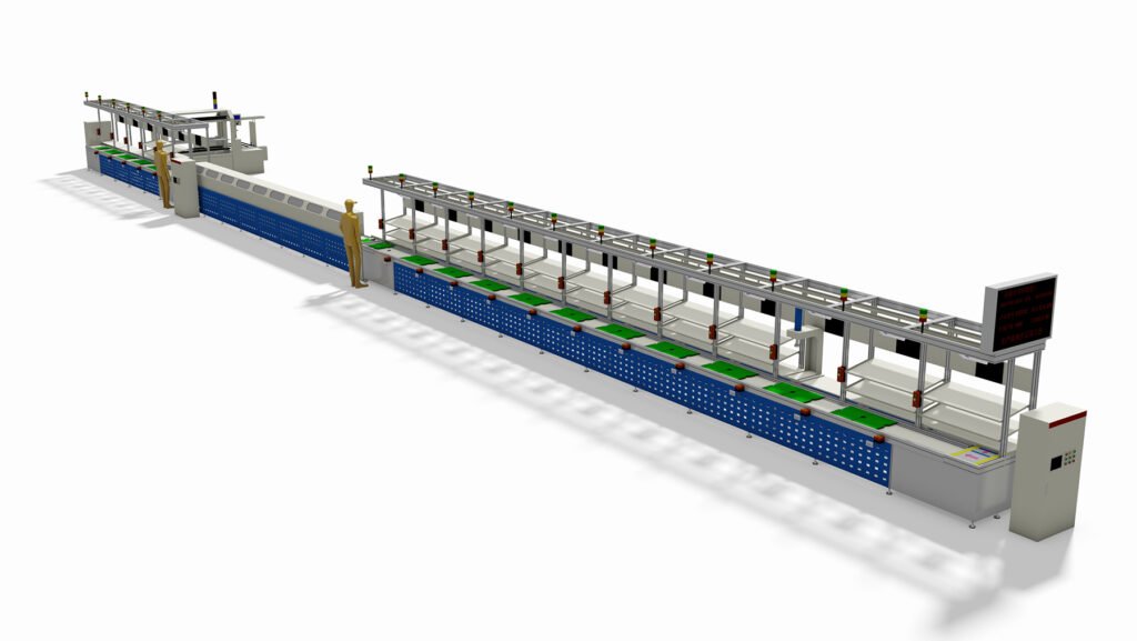
II. Core Structural Composition (by Functional Partition)
The assembly line adopts an overall modular design, consisting of five core parts: conveying system, tooling system, workstation system, control system and auxiliary system. All parts work together to ensure the smooth and efficient assembly process. The specific structure is as follows:
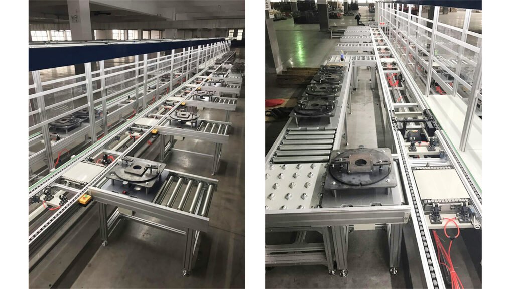
(I) Conveying System (Core Power Unit)
The conveying system is the “skeleton” of the assembly line, responsible for driving the tooling plate and electric tool workpieces to move according to the preset rhythm. The core components include:
- Differential Chain: 2.5x or 3x speed differential chain is adopted (3x speed is the mainstream), composed of inner chain plates, outer chain plates, rollers, sleeves, etc., divided into rolling part and locking part. The rollers are in contact with the track and the tooling bottom plate, and the rollers are meshed with the sprockets. The speed increasing effect is realized by the radius difference, so that the moving speed of the tooling plate reaches 2-3 times the chain speed, which can quickly complete the transfer between workstations and improve production efficiency. At the same time, it adapts to the precise rhythm demand of electric tool assembly. The material is high-strength carbon steel or stainless steel, and the surface is treated with rust and wear resistance to extend the service life. The load-bearing capacity can reach ≤200kg/m (custom heavy-duty specifications are available), with stable operation without jamming and low noise (≤75dB when running at full speed);
- Drive Device: Composed of frequency conversion speed-regulating motor, reducer, drive sprocket and coupling, it provides power for chain operation. It adopts frequency conversion control technology, which can realize stepless speed regulation of 0.5-5m/min, adapting to the assembly rhythm of different electric tools (such as slow rhythm for complex final assembly processes and fast rhythm for simple pre-assembly processes). The motor power is customized according to the length of the line body (conventional 0.75-3kW), with stable operation and low energy consumption. It can accurately connect the drive shaft through the coupling to ensure stable and lossless power transmission. The maximum length of single-section drive is 40m, and ultra-long can be driven in sections and spliced;
- Tensioning Device: Installed at the end of the assembly line, composed of tensioning seat, tensioning sprocket, adjusting bolt or slider, used to adjust the tightness of the differential chain, ensuring that the chain sag is controlled within 1%-2% of the center distance, avoiding tooling plate offset caused by loose chain, or increased motor load and accelerated chain wear caused by over-tightening. It can be adjusted in real time according to chain wear to ensure conveying stability, extend chain service life, and adapt to the dynamic adjustment demand of line body length;
- Conveying Track: Special extruded aluminum alloy profile track (conventional) or non-standard steel track (special demand) is adopted, with anodized surface, wear-resistant and corrosion-resistant, used to support the operation of chain and tooling plate, ensuring that the levelness and straightness error of the track is ≤1mm/m, and the tooling plate moves smoothly along the track without offset or jamming. The effective width of the track is ≤3m (preferably within 1000mm), which can be customized according to the size of the tooling plate. The conventional working height of the line body is 600-800mm (commonly 750mm), and the special height can be customized on demand, adapting to the comfort of workers’ operation and the demand of electric tool assembly. The spatial form can be divided into ground type and suspended type, adapting to different workshop layouts;
- Frame: Made of high-strength aluminum alloy profile or carbon steel welding, used to fix components such as track, drive device and tensioning device. The overall structure is stable, and it can be designed as linear, U-shaped, circular, etc. according to the workshop layout. The length of single section is ≤45m (preferably within 15000mm), and the distance between workstations is 1000-2000mm, which can be flexibly adjusted according to the number of electric tool assembly processes. The guardrail is made of PA or aluminum alloy profile to ensure operation safety, and at the same time facilitate workers’ loading and unloading and process operation. It can be designed as plane left-right multi-section circulation, upper-lower three-dimensional multi-layer circulation and other structures to improve the utilization rate of workshop space.
(II) Tooling System (Workpiece Bearing Unit)
The tooling system is the “bearing platform” of electric tools. Its core function is to fix and position the workpiece, ensure the stable posture of the workpiece during assembly, and facilitate the docking of workers and automatic equipment. The core components include:
- Tooling Plate: As the direct carrier of the workpiece, the material is steel plate, engineering plastic plate or wood plate. The thickness is customized according to the weight of the electric tool (conventional 15-20mm), and the surface is flat and smooth. According to the shape and size of different types of electric tools, special positioning fixtures (such as buckles, positioning pins, clamping cylinders, etc.) can be customized to achieve precise positioning of the workpiece. The positioning error is ≤±1mm (high precision can reach ≤0.05mm), avoiding workpiece offset during assembly and causing assembly error. The tooling plate can be reused, moving with the chain to complete the corresponding assembly processes at each workstation. Some tooling plates can be equipped with conductive bars, which cooperate with the conductive wheels in the line body to realize live conveying, meeting the needs of electric tool aging testing, power-on debugging and other processes. The size of the tooling plate matches the width of the track, which can be flexibly replaced to adapt to the production needs of multiple varieties. At the same time, the edge of the tooling plate is equipped with a buffer device to avoid collision between workstations and damage to the workpiece or the tooling itself;
- Positioning and Blocking Device: Each workstation is equipped with a pneumatic stopper (mainstream) or a mechanical stopper, composed of a cylinder, a blocking block and a sensor. When the tooling plate moves to the target workstation, the sensor triggers a signal, the stopper extends to accurately position the tooling plate, ensuring that the tooling plate remains stationary during assembly. After assembly, the stopper retracts, and the tooling plate enters the next workstation with the chain. It has precise positioning and rapid response, which can effectively improve assembly accuracy. At the same time, it can realize the rotation and translation of the tooling plate with the lifting and rotating and lifting and moving mechanisms in the line, meeting the needs of complex assembly processes, adapting to the needs of multi-angle assembly and detection of electric tools. Some workstations can be equipped with lifting and positioning mechanisms to further improve positioning stability and facilitate high-precision assembly operations (such as screw fastening and line connection);
- Tooling Fixture: Used with the tooling plate, customized according to the specific model of the electric tool. It is made of wear-resistant and non-slip materials, which can quickly clamp and release the workpiece, facilitating workers’ loading and unloading, and at the same time protecting the workpiece surface from scratches and collisions during assembly. The fixture can be quickly disassembled and replaced, adapting to the co-production of multiple types of electric tools without overall adjustment of the line body structure, reducing the model change cost and improving production flexibility. Some fixtures can integrate a buffer structure to further ensure the stability of the workpiece during assembly and avoid assembly errors caused by vibration.
(III) Workstation System (Assembly Operation Unit)
The workstation system is the core area where workers or automatic equipment complete assembly processes. According to the electric tool assembly process, it is laid out in the order of “pre-assembly – final assembly – inspection – auxiliary – packaging”. Each workstation is equipped with special operating equipment and tools, and the core configuration is as follows:
- Workstation Operating Table: Flush with the assembly line track, the width and height are suitable for workers’ operation (conventional height 750-800mm). The table top is made of anti-static material, which can place assembly tools, components, instructions, etc. Some operating tables are equipped with drawers and shelves to facilitate the storage of tools and components, improve operation convenience and reduce redundant operation time. At the same time, the table top can reserve equipment installation holes according to process needs to adapt to the docking of automatic equipment;
- Special Tools: Configured according to process needs, such as electric screwdrivers (adjustable torque, adapting to the screw fastening needs of electric tools), wire crimpers, wire strippers, torque testers, speed testers, insulation testers, noise detectors, etc. Some tools can be fixed on the operating table to avoid loss and improve operation efficiency. Some processes can be equipped with manipulators to realize automatic screw fastening, component grabbing and other operations, further improving the automation level and reducing labor costs;
- Component Rack: Each workstation is equipped with a special component rack, which places components according to their specifications (such as gears, motors, switches, screws, etc.). The rack is designed as inclined or layered, facilitating workers’ access, reducing access time and improving assembly efficiency. At the same time, it can be equipped with a material shortage alarm device to supplement components in time to avoid production line stagnation;
- Inspection Workstation: A special inspection area equipped with power-on test bench, torque detector, insulation performance tester and other equipment, which can conduct comprehensive inspection on the assembled electric tools, screen unqualified products, and at the same time be equipped with an unqualified product storage box to facilitate subsequent rework. The inspection data can be recorded in real time to facilitate production quality traceability. Some inspection workstations can realize automatic inspection, improving inspection efficiency and accuracy and reducing manual inspection errors;
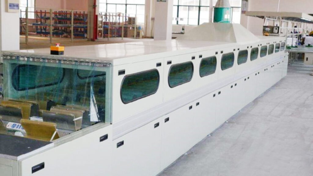
- Aging Test Workstation: Adopting live closed conveying design, with conductive wheels inside the line body and conductive bars on the tooling plate, so that the electric tools move with the line body under live condition to complete continuous aging test. The test time can be adjusted on demand (conventional 30-60 minutes), and after aging, it automatically enters the next process. It can effectively detect the stability and service life of electric tools, screen potential faulty products and improve the qualified rate of finished products. During the aging process, the operation status of electric tools can be monitored in real time, and an alarm will be given in time if there is an abnormality;
- Packaging Workstation: Equipped with packaging table, packaging machine, labeling machine and other equipment. Workers complete the boxing, labeling, packing, packaging and other operations of qualified products. The packaging table can adjust the height and width according to the packaging specifications to adapt to the packaging needs of different sizes. Some packaging processes can be equipped with automatic labeling machines and packaging machines to further improve packaging efficiency and reduce manual labor intensity.
(IV) Control System (Core Command Unit)
The control system is the “brain” of the assembly line, responsible for coordinating the operation of various systems to realize automatic and intelligent control. The core components include:
- PLC Controller: As the core control component, brand PLC (such as Siemens, Mitsubishi, Omron) is adopted, with preset assembly process programs, which can control chain running speed, tooling plate positioning, stopper action, detection equipment operation, etc., to realize the coordinated work of various processes. At the same time, it has program modification and parameter adjustment functions, which can flexibly optimize the assembly process according to production needs and adapt to the model change needs of multi-variety production. It can integrate production data statistics function to record production output, qualified rate, process time and other data in real time, facilitating production management and optimization;
- Touch Screen Operation Panel: Installed at the head or middle of the assembly line, adopting human-computer interaction design, simple and intuitive operation. Workers can set the running speed, adjust workstation parameters, start/stop the production line, check the running status, call production data, etc., through the panel. At the same time, it has a fault alarm function. When the production line breaks down (such as chain jamming, sensor failure, motor failure, etc.), the panel will display the fault location and cause in real time, facilitating workers to quickly troubleshoot and repair, and reducing downtime;
- Sensor System: Including photoelectric sensors, proximity switches, pressure sensors, etc., distributed in each workstation and conveying track, used to detect tooling plate position, whether the workpiece is in place, whether the fixture is clamped, whether components are missing, etc., and transmit the detection signal to the PLC controller to realize precise control, avoid misoperation, and improve assembly accuracy and production safety. At the same time, it can detect the chain running status, motor temperature, etc., to find potential faults in time and give early warning;
- Electrical Control System: Including distribution box, contactor, relay, frequency converter, etc., responsible for providing stable power for each system, controlling motor speed, cylinder action, etc. The frequency converter can realize stepless speed regulation of the motor, adapting to the needs of different assembly rhythms. The distribution box is equipped with leakage protection, overload protection, short circuit protection and other functions to ensure the safety of equipment and workers’ operation, avoid safety accidents and equipment damage caused by electrical faults. At the same time, it can design power configuration according to different national voltage standards to adapt to export needs;
- Emergency Stop Device: Each workstation is equipped with an emergency stop button, and the head, middle and tail of the assembly line are equipped with main emergency stop switches. When an emergency occurs (such as workpiece jamming, workers’ operation error, etc.), workers can quickly press the emergency stop button to stop the production line, ensuring the personal safety of workers and the safety of equipment. At the same time, the system will lock the state after emergency stop, and it can only be restarted manually after troubleshooting to avoid the risk caused by misstart.
(V) Auxiliary System (Guarantee Unit)
The auxiliary system is used to improve the operation stability, operation convenience and production safety of the assembly line. The core components include:
- Lighting System: Each workstation is equipped with LED explosion-proof lighting, which is bright, energy-saving and durable, ensuring that workers have a clear vision during operation, avoiding assembly errors caused by insufficient light. At the same time, the LED lamp has waterproof and dustproof functions, adapting to the workshop production environment;
- Dust Removal System: Some workstations (such as grinding and oil spraying processes) are equipped with small dust removal equipment to collect dust and oil generated during production, keep the workshop environment clean, protect workers’ health, and avoid dust and oil adhering to the workpiece surface, affecting assembly quality;
- Protection System: Both sides of the assembly line are equipped with aluminum alloy guardrails (conventional height 1100mm) to protect workers’ operation safety, avoid workers’ contact with moving parts such as running chains and tooling plates, and prevent workpieces from falling. The guardrails can be provided with openings according to workstation needs to facilitate workers’ loading and unloading, and the openings are equipped with protective doors to improve protection safety;
- Lubrication System: Automatic lubrication device, which regularly adds lubricating oil to moving parts such as differential chain, sprocket and guide rail, reduces component wear, extends equipment service life, reduces maintenance costs, and reduces running noise. The lubrication cycle can be set on demand to realize automatic lubrication without frequent manual operation, improving maintenance convenience;
- Waste Collection System: Each workstation is equipped with a waste box to collect waste screws, waste wires, packaging waste, etc., generated during assembly, facilitating centralized treatment, keeping the workstation clean, avoiding waste accumulation affecting operation, and realizing classified collection of waste, facilitating subsequent recycling and improving resource utilization;
- Emergency Power Supply System: UPS emergency power supply can be optionally equipped. When the workshop has a sudden power failure, the emergency power supply can ensure the short-term operation of core components such as control system and lighting system, facilitating workers to sort out the workstation and protect the workpiece, avoiding workpiece damage and production data loss caused by sudden power failure.
III. Working Principle
The core working principle of the electric tool differential chain assembly line is to use the speed increasing effect of the differential chain, combined with modular layout and automatic control, to realize the continuous and precise assembly of each process of electric tools. The specific working process is as follows:
- Initialization Preparation: Workers place the required components of each workstation on the corresponding racks, check whether the tooling fixtures, detection equipment and control system are normal, set the assembly line running speed, tooling plate positioning parameters, detection standards, etc., through the touch screen operation panel, and complete the pre-production preparation work. At the same time, add lubricating oil to the moving parts and check the tightness of the chain to ensure that the equipment is in normal operation;
- Workpiece Loading: Workers place the electric tool base or core components (such as motor, gearbox) on the special fixture of the tooling plate, and the fixture automatically clamps the workpiece to ensure precise positioning of the workpiece without offset. After loading, workers press the workstation start button to send a signal to the PLC controller;
- Differential Conveying: After receiving the signal, the PLC controller controls the drive motor to start. The motor drives the drive sprocket to rotate through the reducer, and the sprocket drives the differential chain to run along the track. The differential chain realizes the speed increasing effect by the radius difference between the roller and the roller, driving the tooling plate and the workpiece to move to the next workstation smoothly at 2-3 times the speed of the chain. During the conveying process, the sensor detects the position of the tooling plate in real time to ensure precise conveying without jamming or offset;
- Workstation Assembly: When the tooling plate moves to the target workstation, the photoelectric sensor detects the tooling plate signal and transmits it to the PLC controller. The controller controls the stopper to extend to accurately position the tooling plate. Workers or automatic equipment complete the corresponding assembly operations (such as pre-assembling components, screw fastening, line connection, etc.) according to the preset process. After assembly, workers press the workstation completion button, the stopper retracts, and the tooling plate continues to enter with the chain.
We can customize according to the client’s product specifications, production capacity or other requirements.
We provide comprehensive services including design, production, and installation/commissioning.