Electric Lawn Mower Assembly Line—Corded Electric Lawn Mower Assembly Line—Cordless Rotary Lawn Mower Assembly Line
Electric lawn mowers are typical mechatronic products, mainly consisting of the power and energy system (battery, drive/cutting motor, electronic control unit), cutting system, travel transmission system, and control and safety system.
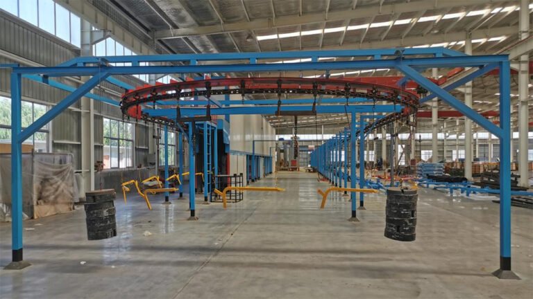
For the large-scale production of linear differential chain-drive electric lawn mowers, the assembly line adopts a unidirectional linear layout aimed at achieving efficient and controllable production. Its core characteristics include process rigidity (fixed sequence ensures stable takt time), deep integration of mechanics and electronics (simultaneous handling of precision mechanical assembly and high-voltage electrical integration), and embedded quality control (online collection of key parameters and full-process traceability). The production line consists of five functional segments: structural assembly, core transmission installation, electrical system integration, final assembly, and testing and validation.
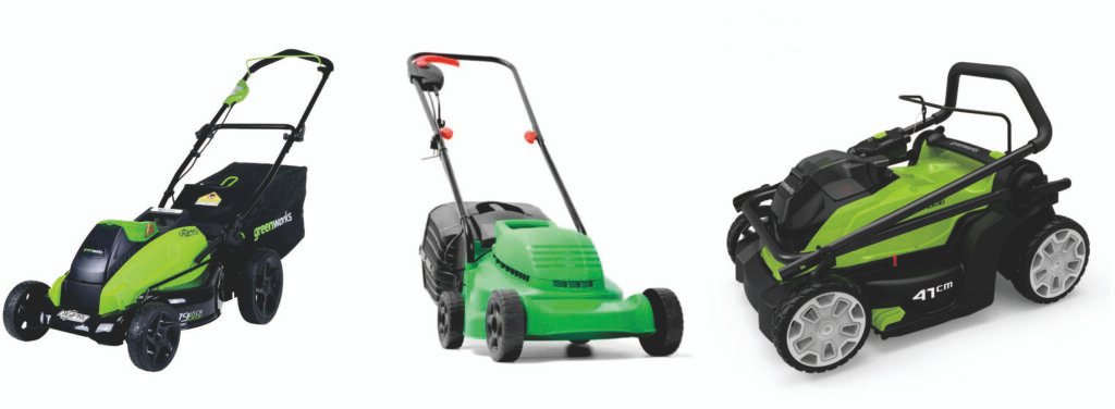
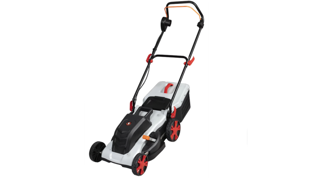
Electric Lawn Mower Assembly Lines are suitable to Assemble/Produce Mowers. (If clients have more requirements or want to produce the other Mowers, welcome to contact us.)
Part I: Electric Lawn Mower: Structure, Assembly, and Inspection Process
I. Product Structure and Functional Modules
Electric lawn mowers can be categorized into AC (corded) and DC (battery) types. The current mainstream is the brushless DC battery-powered mower, with its core modules as follows:
- Power and Energy System
- Drive Motor: Brushless DC motor providing power for travel, typically integrated with a differential or reduction gearbox.
- Cutting Motor: Independent brushless DC motor directly driving the blade disc. Some smaller models may share a motor with the drive system.
- Battery Pack: Rechargeable lithium-ion battery pack, the “heart” of the machine. Includes cells, BMS (Battery Management System), housing, and interface.
- Electronic Control Unit (Controller/ECU): The core “brain”. Receives operator commands (switches, speed levers), controls motor speed, start/stop, and provides protection against overcurrent, overheating, undervoltage, etc.
- Cutting System
- Blade Disc: Mounts the cutting blades (metal or high-rigidity plastic) or nylon line trimmer head.
- Blade/Nylon Line: Components performing the cutting function.
- Protective Shield and Discharge Chute: Ensures safety and guides/collects grass clippings.
- Travel and Transmission System
- Chassis/Frame: The main structural body carrying all components.
- Differential (High-end models) or Fixed Axle Drive: Enables flexible steering.
- Transmission Mechanism: Chain, belt, or gears transmitting power from the drive motor to the wheels.
- Wheels: Front wheels for steering, rear wheels for drive (or all-wheel drive).
- Control and Safety System
- Main Control Handle/Handlebar: Integrates safety start switch (requires simultaneous two-hand press to power on), travel speed control lever/knob, cutting height adjustment lever.
- Electrical Wiring Harness: The “neural network” connecting battery, controller, motors, switches, and safety sensors (e.g., tip-over shutdown sensor).
- Grass Catcher/Side Discharge/Mulching Module: Attachments for switchable grass clipping management.
II. Assembly Process Flow
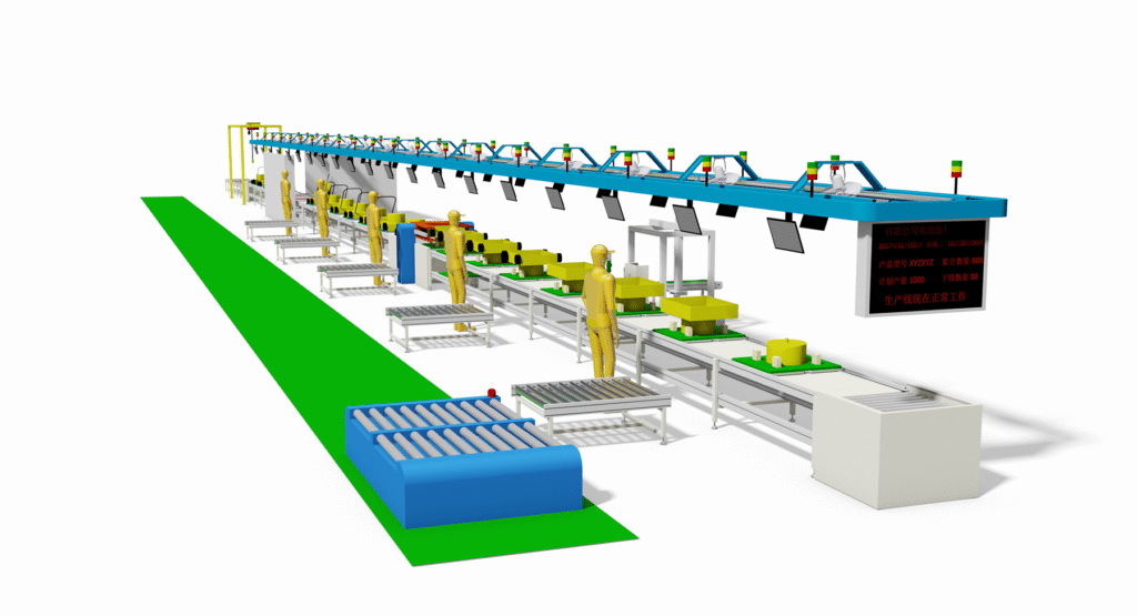
The assembly line follows the principle of “chassis as the backbone, electrical system as the core, sub-assembly before final assembly,” typically using flexible slat conveyors or AGV carts.
Core Process Flow:
Material Preparation → Chassis Pre-assembly → Electrical System Installation → Power & Cutting System Integration → Interior/Exterior Trim & Attachment Installation → Software Flashing & Debugging → Comprehensive Testing → Packaging & Offline
Detailed Main Segments:
- Segment 1: Sub-assembly & Pre-processing
- Battery Pack Sub-assembly Line: Cell sorting, welding into modules, BMS installation, potting/encapsulation, aging test.
- Motor-Transmission Sub-assembly: Assemble drive motor with differential/gearbox, lubricate, test.
- Blade Disc Dynamic Balancing: Balance correction for high-speed rotating metal blade discs.
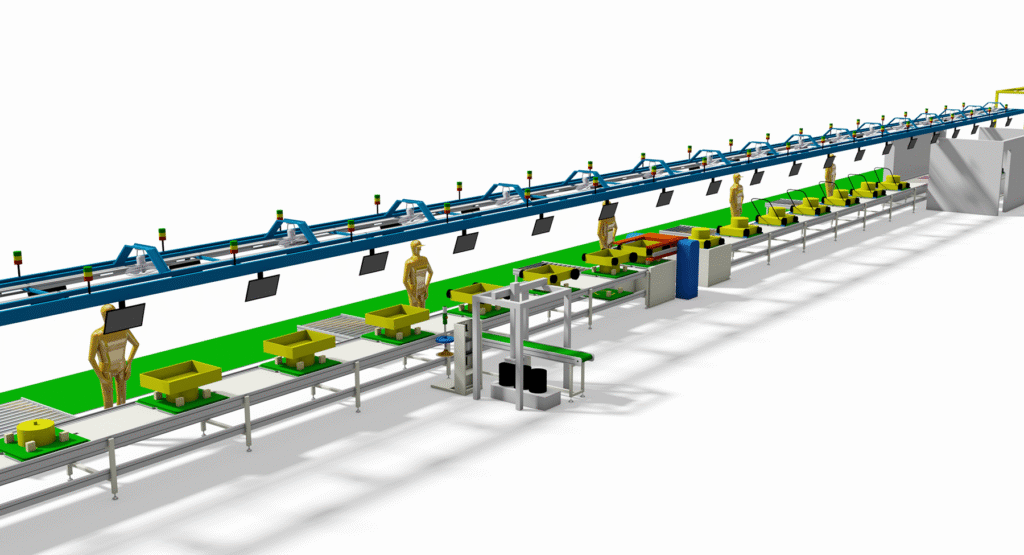
- Segment 2: Main Line Assembly (Chassis as Carrier)
- Station 1-2: Chassis loading, installation of travel wheel set, handlebar bracket.
- Station 3-4: Installation of drive motor assembly, cutting motor assembly.
- Station 5 (Core Electrical Station):
- Install the controller (ECU), fixed in a location with good heat dissipation.
- Route main wiring harness, pre-connect motor and battery interfaces.
- Key Operation: Harness connections must use fool-proof design (color-coding, keyed connectors) and undergo sealing checks (dust/waterproof).
- Station 6: Install battery compartment, safety switches, control panel, and finalize all harness connections.
- Segment 3: Debugging & Testing (Core Segment)
- Station 7: Software & Power-on Self-Test
- Connect diagnostic tool, flash controller firmware, configure parameters.
- Perform first power-on, check BMS communication, sensor status, error codes.
- Station 8: Functional Debugging & Safety Testing
- Safety Switch Test: Verify the two-hand start switch functions correctly.
- Travel Test: Test forward/reverse (if equipped) functions at various speeds on a roller dynamometer, check differential function.
- Cutting Test: Start cutting motor under no-load, check for vibration, abnormal noise, emergency stop function.
- Protection Function Test: Simulate tip-over to verify the tip-over sensor immediately cuts power to the cutting motor.
- Station 9: Comprehensive Performance & Endurance Test (Sampling)
- Simulated load mowing test (using specialized test turf carpet).
- Continuous run test, monitoring motor temperature rise, controller status.
- Battery pack discharge performance test.
- Station 7: Software & Power-on Self-Test
- Segment 4: Final Inspection & Packaging
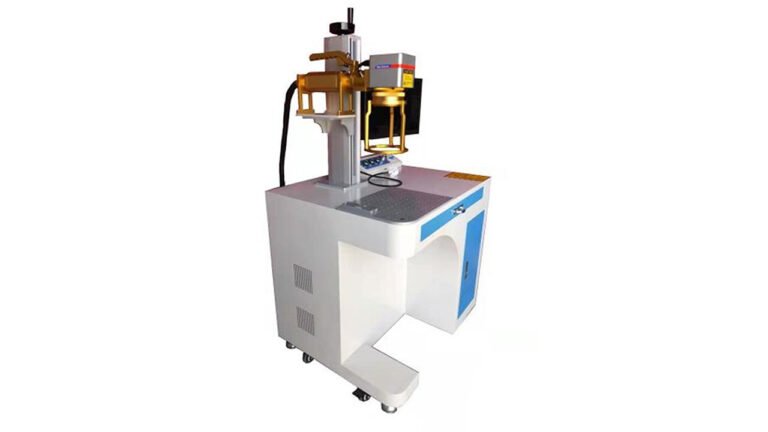
- Station 10: Final visual inspection, cleaning, attaching nameplate, safety labels.
- Station 11: Install attachments like grass catcher, package with charger, manual into carton.
III. Key Inspection Processes & Quality Control Points
- Electrical Safety Testing (100% Mandatory)
- Insulation Withstand Voltage Test: Checks insulation strength between live parts and chassis to prevent electric shock.
- Ground Continuity Test: Ensures all exposed metal parts are effectively grounded (for Class I appliances).
- Leakage Current Test.
- Battery System Specialized Testing
- BMS Function Test: Verification of overcharge, over-discharge, overcurrent, short circuit, and temperature protection functions.
- Battery Pack EOL (End of Line) Test: Measures internal resistance, voltage, capacity, and performs several charge/discharge cycle tests.
- Mechanical & Functional Testing
- Critical Torque Verification: Bolts for chassis and blade fixation require torque wrenches with traceable data.
- Noise & Vibration Test: Measures no-load and load noise in an anechoic chamber, evaluates vibration levels.
- Cutting Sharpness & Uniformity Test (Sampling or bench test).
- Software & Information Management
- MES System Integration: Each product has a unique Serial Number (SN), recording all critical component (battery, motor, controller) serial numbers, test data, and operator information for full lifecycle traceability.
- Fault Diagnostic Port: Reserved diagnostic interface for after-sales service.
IV. Core Differences from Gasoline Lawn Mowers
| Feature | Electric Lawn Mower | Gasoline Lawn Mower |
|---|---|---|
| Power Source | Battery + Motor | Gasoline Engine |
| Core Assembly | Electrical system integration, software flashing, safety testing | Fuel system, mechanical transmission, exhaust system |
| Inspection Focus | Electrical safety, BMS, software functions, EMC | Emissions, fuel consumption, mechanical vibration, ignition system |
| Noise & Maintenance | Low noise, simple routine maintenance | High noise, requires regular oil changes, air filter, spark plug replacement |
| Production Environment | Clean, high anti-static requirements | Tolerates some oil residue, high ventilation requirements |
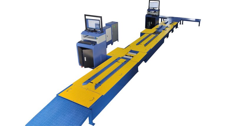
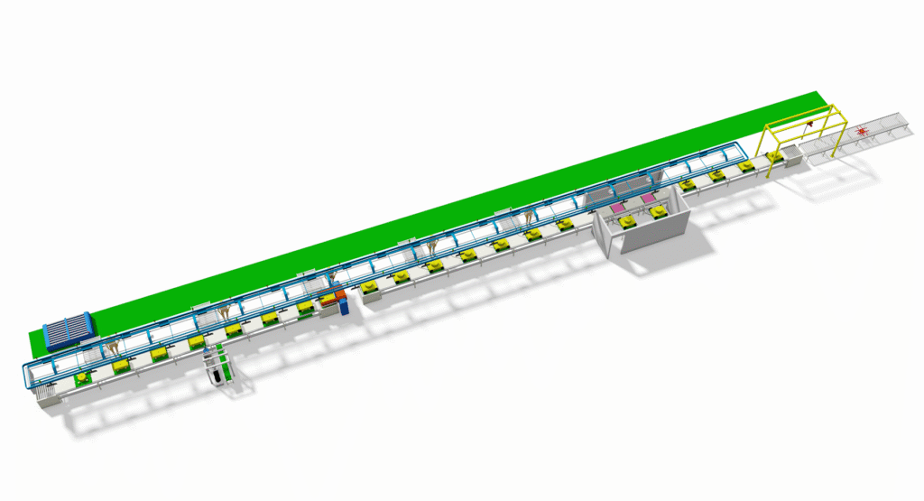
Part II: Overall Description of Linear Differential Chain-Drive Electric Lawn Mower Assembly Line
I. Production Line Design Positioning
The linear differential chain-drive electric lawn mower assembly line is a linear flow system designed for large-scale standardized production, specifically for products with mature structures and stable processes. The entire line adopts a unidirectional flow layout, emphasizing process continuity, controllable cycle times, and production traceability. It effectively supports production capacity targets according to customers’ requests.
II. Core Characteristics of the Production Line
- Rigid and Efficient Process Flow
All operations are arranged in the fixed sequence of Chassis → Transmission → Electrical → Final Assembly → Testing, forming an irreversible linear production flow. This facilitates production planning, control, and efficiency optimization. - Deep Integration of Mechanics and Electronics
Simultaneously handles precision mechanical assembly (differential gear meshing accuracy, chain tension control) and electrical system integration (high-voltage battery pack installation, controller calibration), achieving integrated electromechanical commissioning. - Embedded Quality Control
Key process parameters (torque, tension, electrical characteristics) are automatically collected via online inspection equipment and linked to the product identification code, establishing a fully digitalized quality record for the entire process.
III. Key Technical Configuration
- Conveyor System: Utilizes Differential Chain-Drive conveyors or synchronized slat conveyors equipped with lift-and-locate mechanisms to ensure stable transfer and precise positioning of the chassis between workstations.
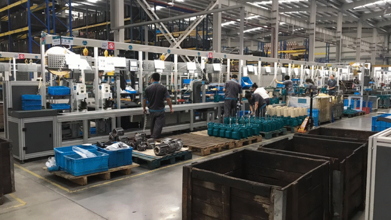
- Material Supply: Implements a modular trolley (SPS) supply model. Large components (e-drive assembly, battery pack) are delivered via AGV point-to-point supply, synchronizing material flow with the production takt time.
- Data System: Integrates barcode scanners, smart tools, and testing equipment through an MES system to enable real-time monitoring of process parameters, automatic archiving of quality data, and visualization of production status.
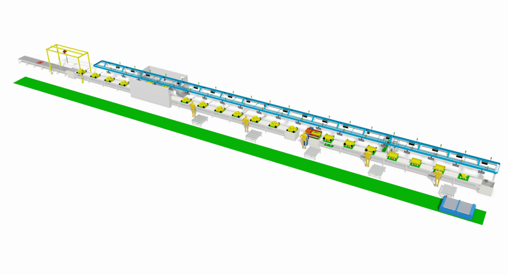
IV. Production Process Overview
The entire line is divided into five consecutive functional segments:
- Structural Segment: Completes frame pre-treatment, travel system, and basic structure assembly.
- Core Segment: Performs e-drive differential assembly installation, chain drive system tensioning, and initial adjustment.
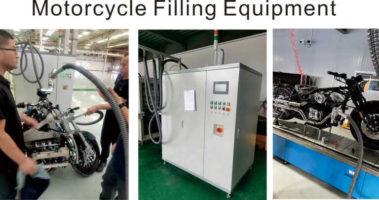
- Electrical Segment: Completes high-voltage battery pack integration, controller and wiring harness installation, and performs initial power-on diagnostics.
- Final Assembly Segment: Installs the cutting system, protective housing, and control components.
- Verification Segment: Executes differential function tests, load simulation tests, safety compliance checks, and final packaging.
V. Core Advantages of the Production Line
- Efficiency First: Driven by linear takt time, eliminates process waiting, with theoretical production efficiency potentially exceeding 92%.
- Controllable Quality: Implements error-proofing through 31 online inspection points, achieving 100% traceability for key quality data.
- Simplified Management: The unidirectional flow design reduces on-site scheduling complexity and supports visual production management.
VI. Applicable Scenarios and Limitations
Best Suited For: Manufacturing scenarios requiring stable product platforms, high annual output, and moderate automation levels.
Main Limitations: Less adaptable to product changes; higher cost for line reconfiguration; more suitable for concentrated production of a single platform or a small number of product variants.
We can customize according to the client’s product specifications, production capacity or other requirements.
We provide comprehensive services including design, production, and installation/commissioning.