
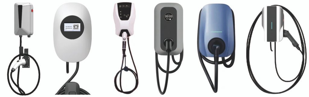
An AC charging pile consists of pile body, indicator lights, card reader, emergency stop button, charging gun, main control module and other components. Its assembly includes component preparation, module assembly, whole machine integration and grounding. Testing covers visual, electrical safety, function, environmental adaptability and other items. The AC charging pile assembly line, with standardized and efficient design, realizes mass production, including 6 functional areas, ensuring product consistency and meeting factory standards.
AC Charging Pile Assembly Lines are suitable to Assemble/Produce AC charging piles. (If clients have more requirements or want to produce the other charging piles or other chargers, welcome to contact us.)
Part I. Structure, Assembly Process and Testing Process of AC Charging Pile
Structure of AC Charging Pile
An AC charging pile is mainly made up of these key parts:
- Pile body: Usually made of steel or aluminum alloy, it’s the supporting and protective frame of the charging pile.
- Indicator lights & display screen: Show the pile’s working status and parameters like charging progress, voltage and current, so users can check how the charging is going.
- Card reader: Lets users start charging and pay by swiping a card (e.g., RFID or IC card), a common way to use the pile.
- Emergency stop button: Shuts down the pile at once in an emergency to keep users and the equipment safe.
- Charging gun: Connects the pile to the car’s charging port to charge the car. According to the national new standard, AC charging guns have 7 holes.
- Main control module: The “brain” of the pile. It controls the whole operation and data processing—like identifying the car model, confirming charging needs, and setting the right charging power.
- Other components: Circuit breakers, surge protectors, relay modules, terminal blocks and power supply modules. These parts ensure the pile runs stably and safely.

Assembly Process of AC Charging Pile
- Prepare components: Check that all parts are the right model and size, and no damage or deformation (e.g., no scratches/cracks on the pile body, no bent pins on electronic parts).
- Assemble electrical modules: Install circuit breakers, contactors and relays on the circuit board or distribution box. Wire them as designed, make sure connections are tight (e.g., weld or crimp wires to component pins, and insulate the connections).
- Assemble control & communication modules: Fit the main control MCU and communication modules (e.g., CAN bus, Ethernet, Wi-Fi). Connect signal and power lines correctly, and plug all communication cables into the right ports.
- Assemble human-machine interaction parts: Install the display screen, indicator lights, card reader and emergency stop button in their fixed positions on the pile body. Connect their data and power lines tightly (e.g., fasten the display’s flat cable to the main control board).
- Assemble the charging gun: Connect the gun’s plug and cable to the internal electrical terminals firmly. Pay attention to the cable’s bending radius—don’t bend it too much to avoid damage. Then fit the gun’s protective cover and fixing device.
- Whole machine assembly: Put the assembled electrical, control and interaction parts into the pile body, fix them tightly to make the internal layout compact and reasonable. Connect all the wires between different parts (e.g., run power lines from the distribution box to the main control board and power supply module).
- Grounding treatment: Connect all metal parts (e.g., pile shell, bracket) to the grounding electrode firmly. The grounding resistance must meet national standard requirements (e.g., use galvanized flat steel or copper core wire for grounding).
Testing Process of AC Charging Pile
- Visual inspection: Check the pile’s appearance for damage, a smooth surface and clear labels. Make sure the pile is fixed firmly and all parts are connected tightly.
- Electrical safety test:
- Insulation resistance test: Use an insulation resistance tester— the value must not be lower than the standard.
- Dielectric strength test: Apply the specified voltage and check for no breakdown or flashover.
- Ground continuity test: Ensure reliable grounding and qualified grounding resistance.
- Leakage current test: Check that the leakage current during operation is within the allowed range.
- Function & performance test:
- Test charging start/stop: Make sure the pile can start and stop charging normally.
- Test emergency stop: Press the button and check that the pile shuts down immediately.
- Test metering accuracy: Compare with standard metering equipment to verify accurate charging measurement.
- Test over/under voltage protection: Simulate over/under voltage conditions and check that the pile cuts off power in time.
- Environmental adaptability test:
- High/low temperature test: Put the pile in a temperature test chamber and test its working performance under different temperatures.
- Dust & water proof test: Check that the pile’s protection grade (e.g., IP54) meets the standard.
- Interoperability test:
- Test interface compatibility: Ensure the charging port can connect and work with different car models.
- Test communication protocol consistency: Verify that the pile’s communication with the car’s BMS meets national standards.
- Electromagnetic compatibility (EMC) test:
- Radiated emission test: Measure the electromagnetic radiation the pile emits to the outside.
- Conducted emission test: Check the electromagnetic interference the pile transmits through power lines.
- ESD immunity test: Simulate static electricity discharge and test the pile’s anti-interference ability.
PART II. AC Charging Pile Assembly Line Instructions
The AC charging pile assembly line is the core carrier for large-scale and standardized production of charging piles. With the core process of “component pre-installation → modular assembly → whole pile integration → initial inspection and commissioning”, it balances assembly efficiency and product consistency, and is suitable for mass production of various AC charging piles (single-phase/three-phase) for household and commercial use. The entire process complies with electrical safety specifications and industry assembly standards to ensure each product meets factory requirements.
I. Core Positioning and Design Principles of the Assembly Line
1. Core Positioning
It realizes the full-process assembly of AC charging piles from scattered components to finished products, covering the precise assembly of electrical components, structural components and human-machine interaction components. It simultaneously completes wiring connection, grounding treatment and initial function inspection, replacing scattered manual assembly, reducing human errors and improving production efficiency (the capacity of a single line can reach 50-200 units/day according to configuration).
2. Design Principles
- Standardization: All assembly processes, tooling fixtures and operating specifications are unified, complying with the new national standards and industry technical requirements to ensure the assembly consistency of products in different batches;
- Safety: Divide electrical assembly area and high-voltage testing area, set up insulation protection, electrostatic protection and emergency shutdown devices to avoid risks such as electrical short circuits and electrostatic damage to components;
- Efficiency: Adopt the mode of “flow production + modular pre-installation”, reasonably allocate process rhythm, reduce process waiting time, and adapt to mass production needs;
- Scalability: Reserve process interfaces, which can adjust the assembly process according to the charging pile model (single-phase/three-phase) and power specifications to adapt to product iteration and upgrading.
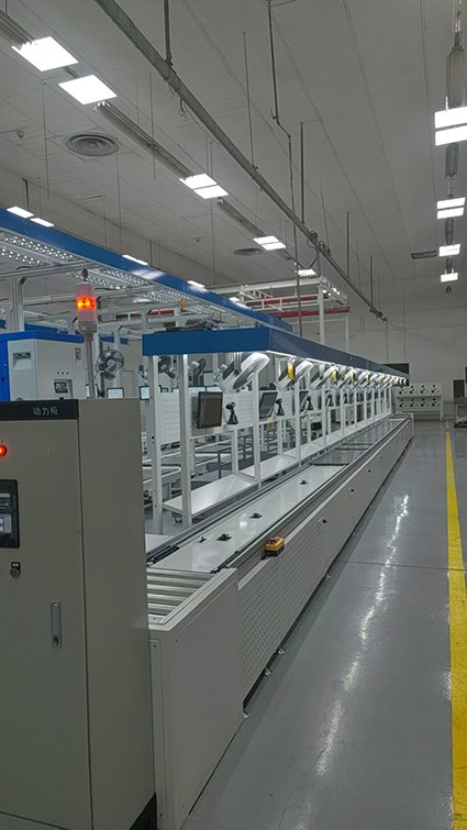
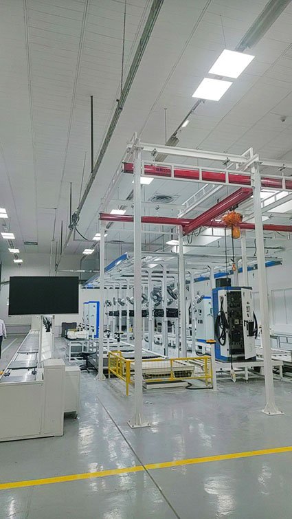
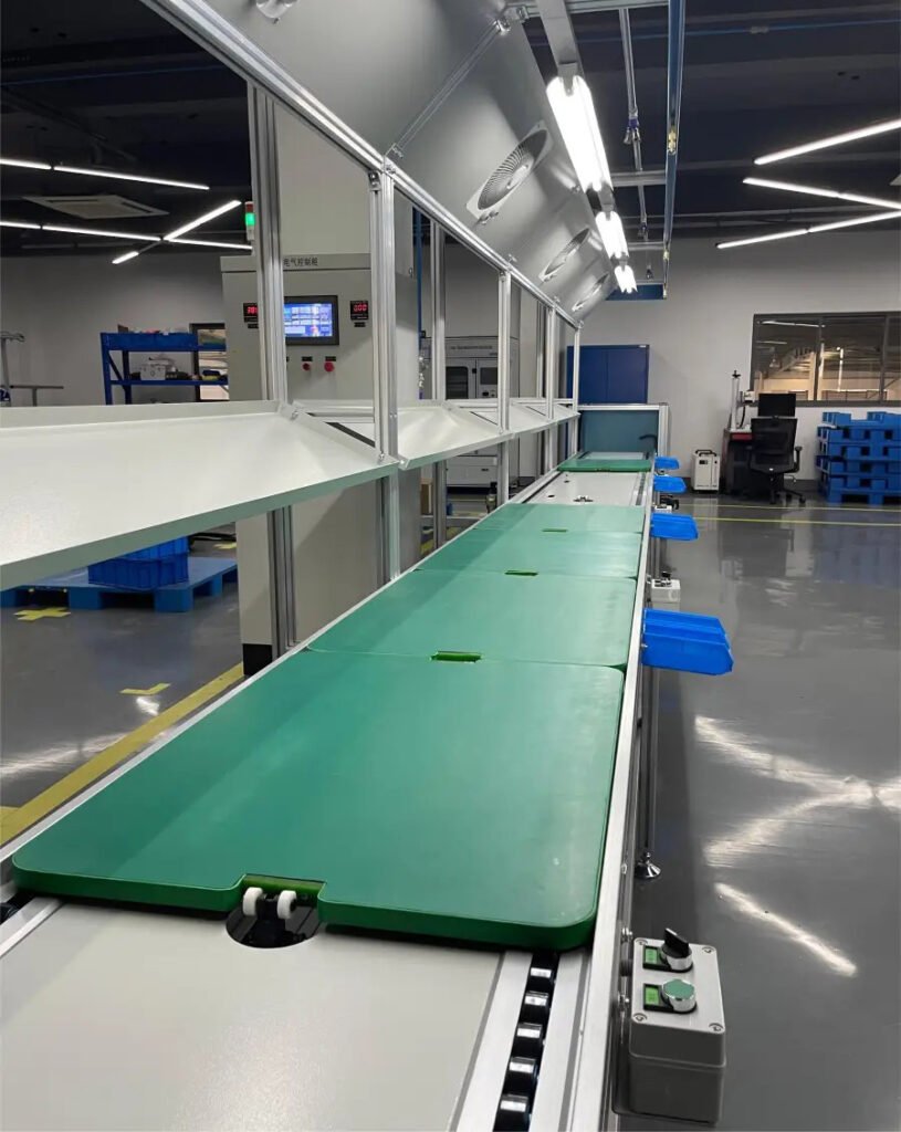
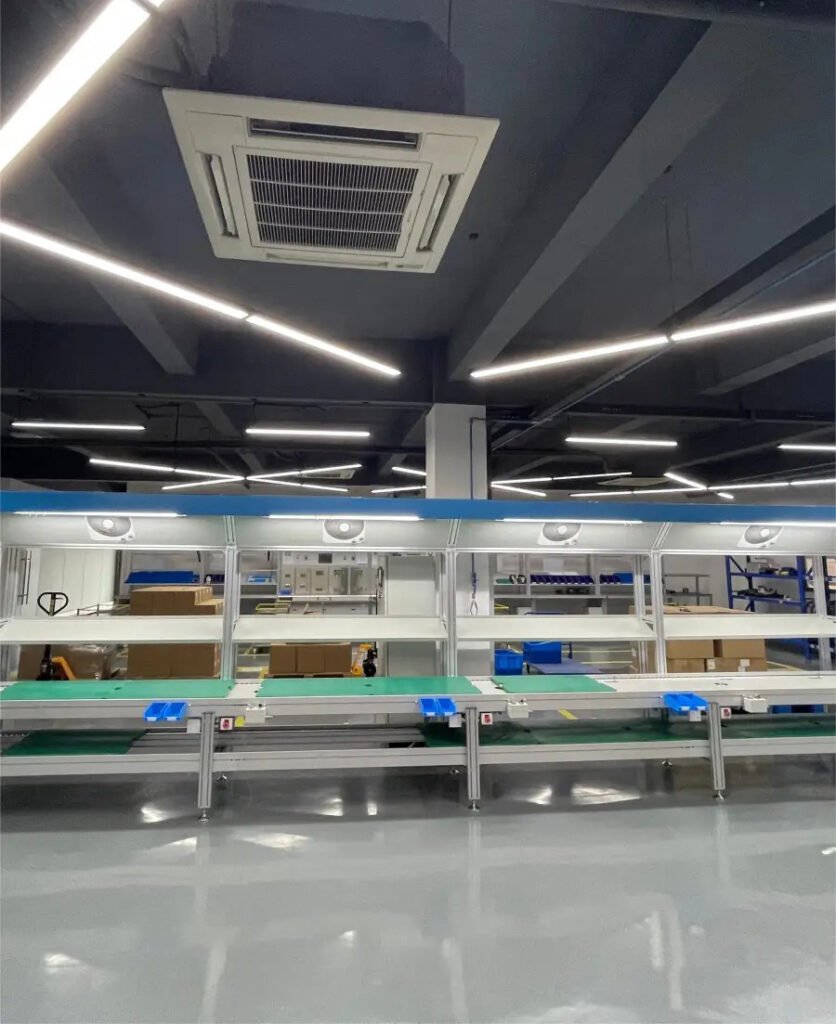
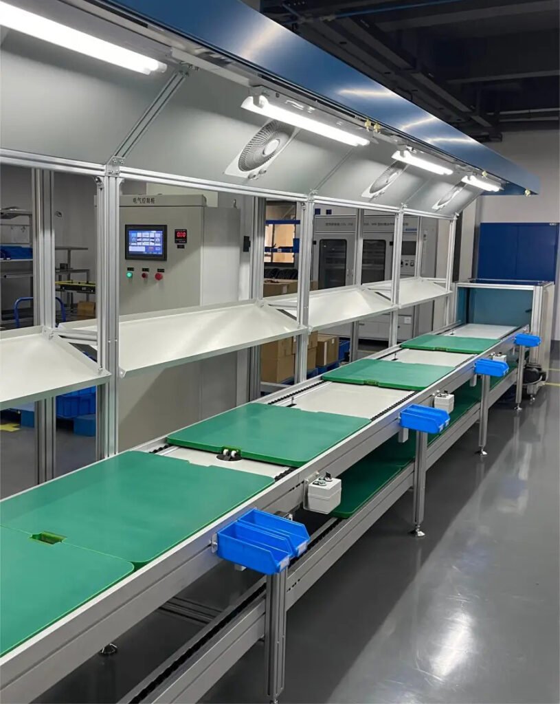
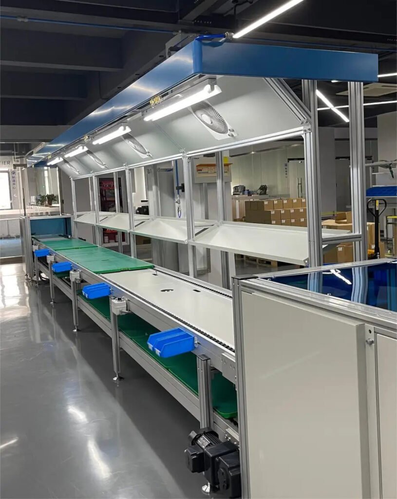
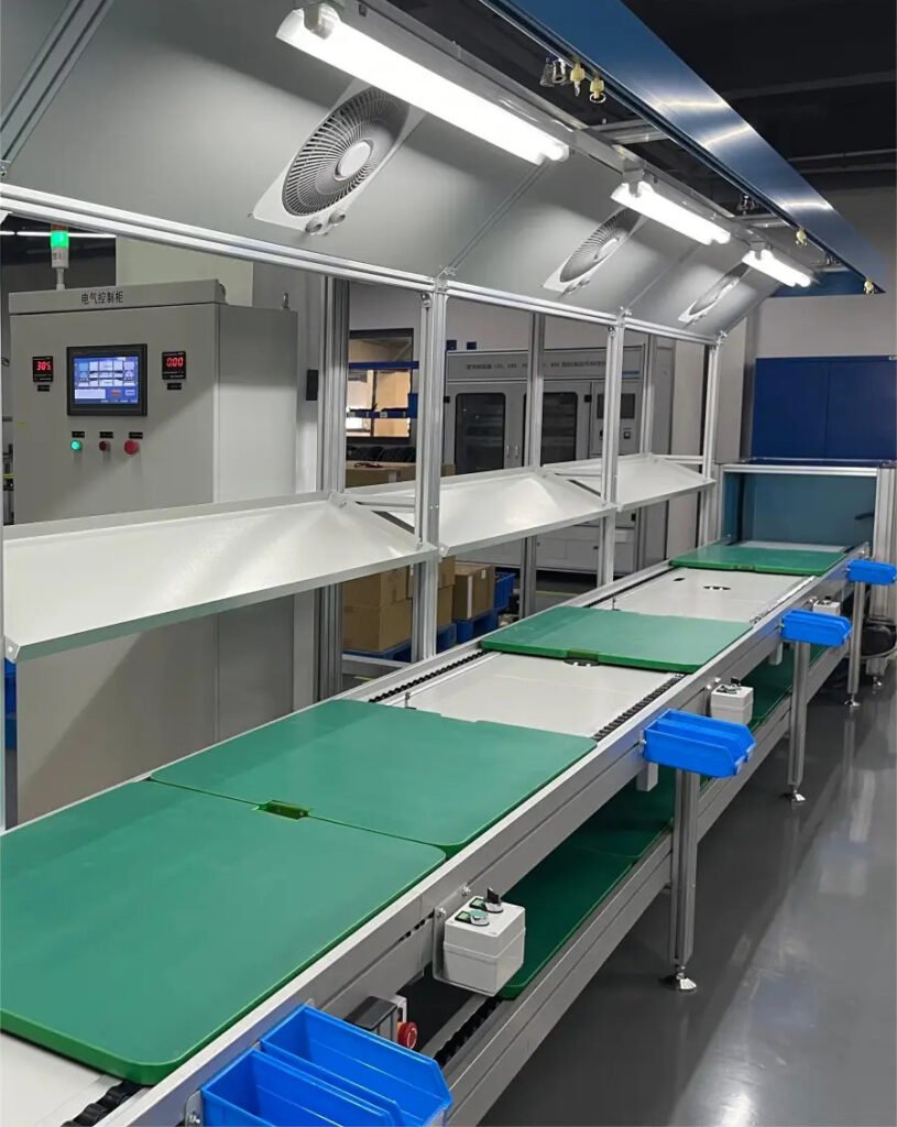
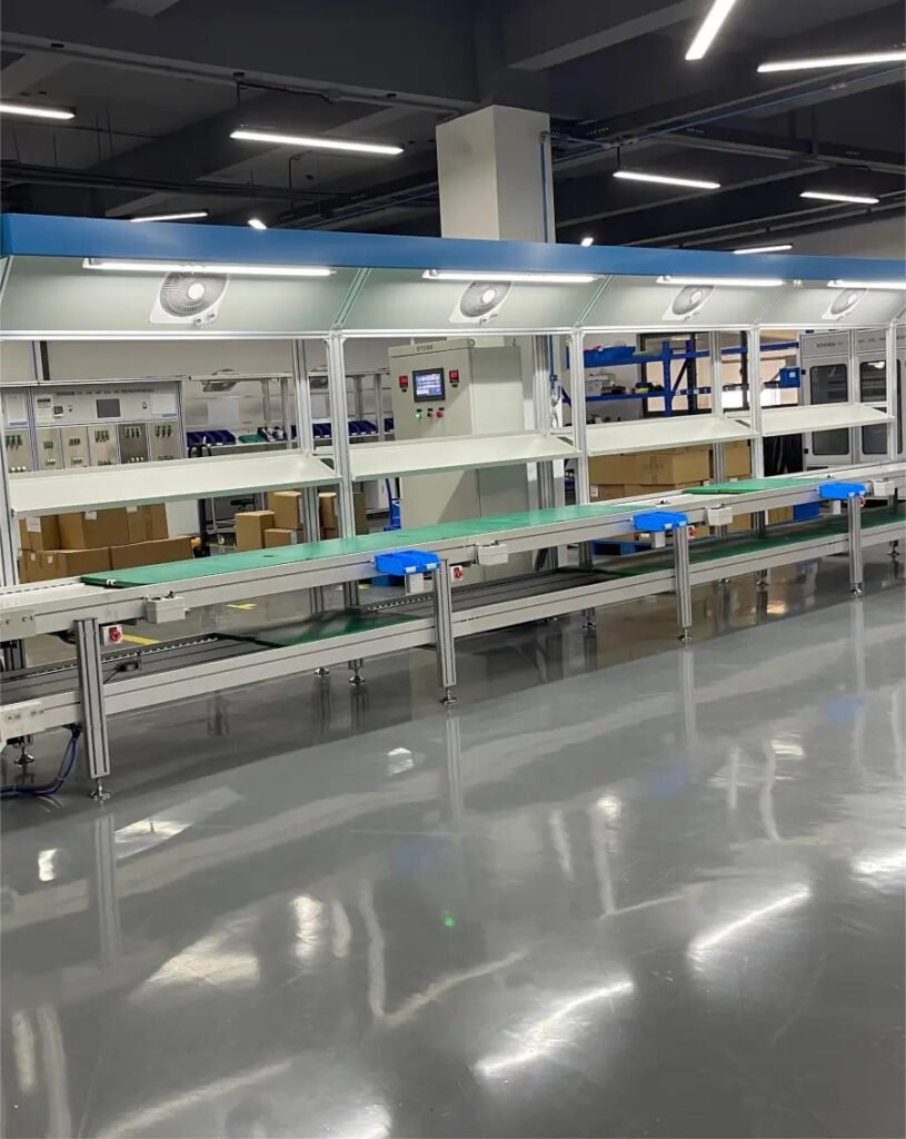
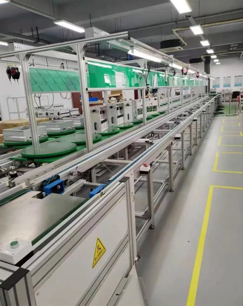
II. Overall Layout and Equipment Configuration of the Assembly Line
The assembly line adopts a linear flow layout, which is divided into 6 functional areas in turn from the feeding end to the discharging end. Each area is equipped with special tooling equipment to realize smooth process connection. The specific layout and equipment are as follows:
1. Feeding and Component Pretreatment Area (Starting End)
Core Function: Complete the incoming inspection, cleaning and pretreatment of all components to ensure they meet assembly requirements and prevent unqualified components from entering the assembly process.
Key Equipment: Incoming inspection table, electrostatic precipitator, component sorting rack, label printer;
Work Content: Verify the model and specification of components (such as main control module, circuit breaker, charging gun cable), check for no damage to the appearance and no deformation of pins, clean dust and oil on the surface of components, perform electrostatic protection treatment on key components (such as electrical components), and paste assembly labels.
2. Modular Pre-installation Area
Core Function: Pre-assemble scattered components into 3 core modules in advance to reduce the pressure of main line assembly and improve assembly accuracy, which is a key link in AC charging pile assembly.
Subdivided Pre-installation Units and Equipment:
- Electrical Module Pre-installation Unit: Tooling fixtures, terminal crimping machine, welding machine, insulation tester; Work Content: Assemble circuit breakers, relays, surge protectors, terminal blocks, etc. onto the electrical mounting plate, complete wire welding and terminal crimping, and test insulation performance.
- Control and Communication Module Pre-installation Unit: Anti-static workbench, flat cable crimping machine, communication interface tester; Work Content: Assemble main control MCU, CAN bus/Ethernet module, Wi-Fi module onto the control board, connect signal lines and power lines, and test the conductivity of communication interfaces.
- Human-Machine Interaction Module Pre-installation Unit: Display assembly tooling, button fixing fixtures; Work Content: Assemble display screen, indicator lights, card reader and emergency stop button onto the panel, connect flat cables and power lines, and ensure normal display and smooth button pressing.
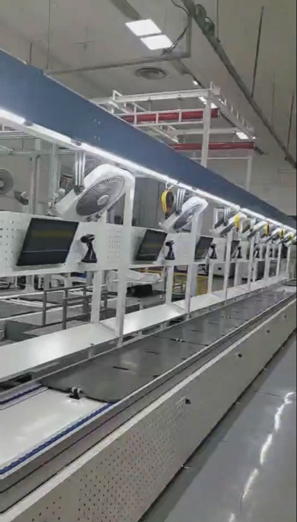
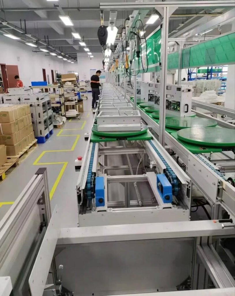
3. Whole Pile Assembly Main Line Area (Core Area)
Core Function: Integrate and assemble the 3 pre-installed modules with structural components such as pile body and charging gun, and complete the mechanical fixation, main line connection and grounding treatment of the whole pile.
Key Equipment: Assembly line conveyor (belt/chain type), pile body fixing tooling, torque wrench, wire sorting fixture;
Work Process (in rhythm order): ① Pile body positioning and fixation → ② Electrical module installation and fixation → ③ Control module installation and main line connection → ④ Human-machine interaction panel installation and fitting → ⑤ Charging gun cable connection and fixation → ⑥ Wire sorting and bundling → ⑦ Grounding device installation and connection.
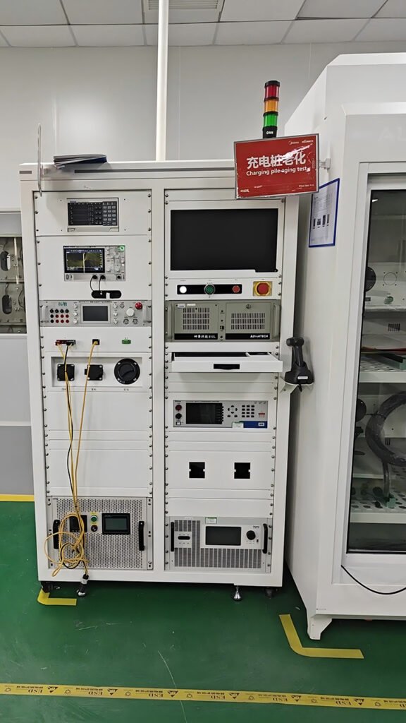
4. Initial Inspection and Commissioning Area
Core Function: Conduct initial electrical safety inspection and function commissioning on the assembled whole pile, identify potential problems during assembly, and ensure the whole pile can operate normally.
Key Equipment: Insulation resistance tester, leakage current tester, multimeter, charging pile function debugger;
Work Content: ① Initial Electrical Safety Inspection: Test insulation resistance and ground continuity, and check for wire short circuits and excessive leakage current; ② Function Commissioning: Simulate the charging process, test charging start/stop, display screen display, card reader identification and emergency stop button function, and confirm normal communication of each module; ③ Appearance Re-inspection: Check the assembly gap of the pile body, the firmness of component fixation and the standardization of wire bundling.
5. Cleaning and Packaging Area
Core Function: Conduct comprehensive cleaning, label pasting and packaging on the qualified piles after initial inspection to ensure factory protection.
Key Equipment: High-pressure air gun, cleaning cloth, packaging machine, foam protective pad;
Work Content: Clean the surface of the pile body and the head of the charging gun, paste product nameplate (model, specification, production date) and safety warning labels, put on dust-proof and waterproof packaging film, put into packaging carton and fill with foam, fix the charging gun, and complete packaging and sealing.
6. Unqualified Product Repair Area (Side Auxiliary Area)
Core Function: Receive unqualified products after initial inspection, identify the cause of failure, conduct repair and re-inspection, ensure that unqualified products can be re-introduced into the production line after repair, and reduce losses.
Key Equipment: Repair workbench, fault detector, spare parts shelf;
Work Specifications: Label unqualified products (indicating fault types, such as “wire short circuit” and “display screen not working”), and after repair, they must go through initial inspection, cleaning and packaging processes again to ensure they meet factory standards.
III. Detailed Explanation of Core Assembly Processes (in Main Line Order)
1. Pile Body Pretreatment (First Step of Main Line)
Fix the pile body (steel/aluminum alloy material) on the tooling table, check whether the mounting holes and wire troughs inside the pile body are unobstructed, remove burrs and dust, paste insulation gaskets on the mounting surface to prevent short circuits caused by contact between electrical components and the pile body, and pre-treat the grounding terminals (grinding and derusting).
2. Electrical Module Assembly
Fix the pre-assembled electrical module (electrical mounting plate) to the designated position inside the pile body with bolts, control the torque within the specified range (adjust according to the pile body material, generally 8-12N·m) to ensure firm fixation without loosening; Lead out the main cables of the electrical module, reserve sufficient length (facilitating subsequent connection with the control module), bundle the cables neatly, and avoid contact and wear with sharp edges and corners.
3. Control and Communication Module Assembly
Fix the control module above the electrical module, align with the mounting holes and tighten the bolts; Connect the signal lines and power lines of the control module to the corresponding interfaces of the electrical module to ensure the interfaces are fully inserted without loosening (such as CAN bus interface and power interface); After connection, use a multimeter to test the conductivity of the interfaces and check for poor contact.
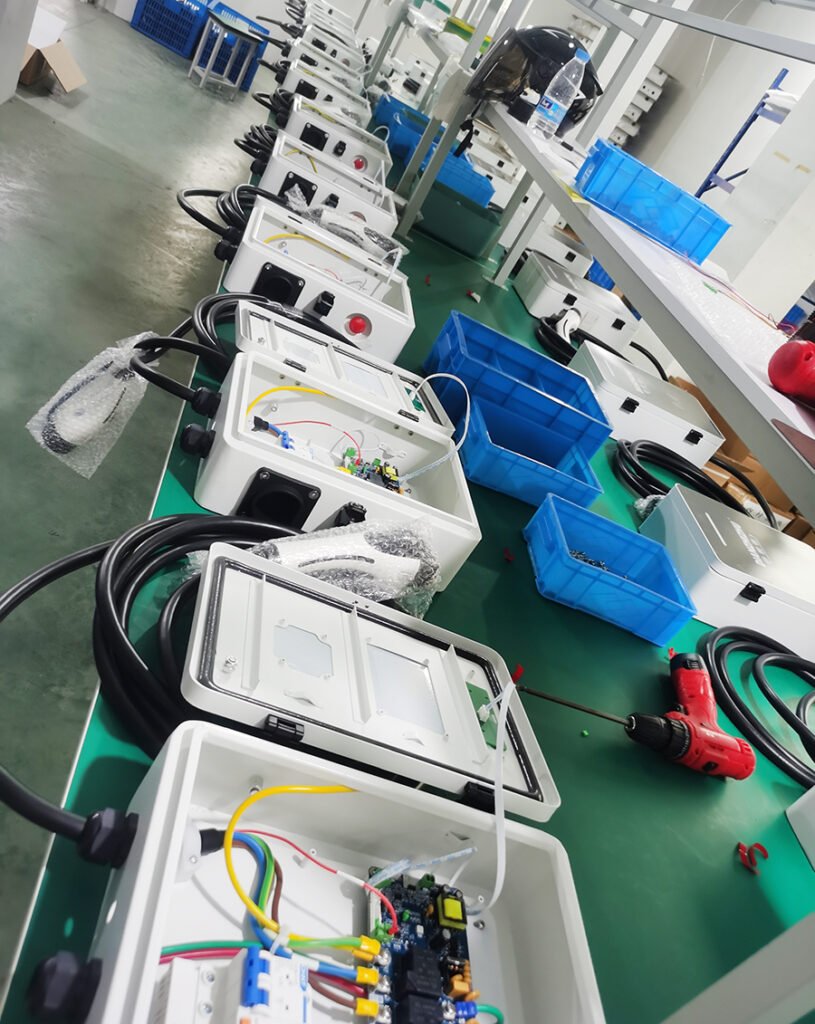
4. Human-Machine Interaction Component Assembly
Align the pre-assembled human-machine interaction panel with the mounting holes on the front of the pile body, fix it with bolts to ensure the panel fits closely with the pile body without gaps; Pass the flat cables and power lines of the panel through the wire trough of the pile body, connect them to the corresponding interfaces of the control module, sort the flat cables to avoid folding and extrusion, and test whether the display screen and indicator lights are normally on, whether the card reader can normally identify cards, and whether the emergency stop button can be triggered normally.
5. Charging Gun and Cable Assembly
Pass the charging gun cable through the cable hole on the side of the pile body, install a waterproof sealing ring at the cable hole (to ensure the protection level meets the standard, generally IP54 and above); Connect the power lines and signal lines inside the cable to the corresponding terminals of the electrical module, tighten the terminal screws, and do a good job in insulation treatment; Fix the charging gun on the gun holder of the pile body, adjust the cable length to ensure smooth insertion and extraction of the charging gun, and no excessive bending or pulling of the cable.
6. Wire Sorting and Grounding Treatment
Use cable ties to bundle all cables inside the pile body neatly according to the direction, and arrange them in categories (power lines and signal lines are bundled separately to avoid interference), and the bending radius of the cables meets the requirements (not less than 10 times the cable diameter); Connect the metal components of the pile body shell, electrical module and control module to the grounding terminal through grounding wires, and the measured grounding resistance value shall not be greater than 4Ω to ensure reliable grounding and avoid electric shock risks.
7. Whole Pile Initial Inspection and Commissioning
Connect the temporary power supply, use an insulation resistance tester to test the insulation resistance of the charging pile (not less than 10MΩ), and use a leakage current tester to test the leakage current (not more than 30mA); Simulate vehicle charging, send charging commands through the debugger, test whether the charging pile can start and stop charging normally, and whether the display screen can accurately display parameters such as voltage, current and charging progress; Test the emergency stop button, which must cut off all power immediately and stop the charging pile from working when pressed; Test the card reader, which can normally identify and trigger the charging process after swiping the card.
IV. Assembly Line Operation Specifications and Safety Requirements
1. Operation Specifications
- Operators must receive professional training, be familiar with the operation process of each process, the use method of equipment, master the structure of charging piles and electrical safety knowledge, and can only take up the job after passing the assessment;
- All components must be assembled according to the corresponding labels, mixing components of different models and specifications is strictly prohibited, and process records shall be made during assembly to facilitate traceability;
- Strictly control the bolt torque and cable connection force during assembly, avoid damage to components due to excessive torque and loosening due to insufficient torque, and the cable connection must be firm without poor contact or wrong connection;
- Process connection must be smooth, and the next process can only be entered after the previous process is qualified. Unqualified products must be marked immediately and transferred to the repair area, and are strictly prohibited from entering the next process;
- After the assembly is completed, the operator must sign and confirm on the process record sheet to ensure the assembly process of each product is traceable.
2. Safety Requirements
- The assembly workshop must be equipped with electrostatic protection facilities (anti-static floor, anti-static wristband, anti-static workbench), and operators must wear anti-static wristbands before going to work to avoid electrostatic damage to electronic components;
- Carrying flammable and explosive items in the electrical assembly area and commissioning area is strictly prohibited, dry powder fire extinguishers and emergency power supplies must be equipped, and the emergency shutdown device must be inspected regularly to ensure it is normal;
- Temporary power supply is required during commissioning, and operators must wear insulating gloves and insulating shoes to avoid direct contact with exposed electrical components and prevent electric shock;
- During the operation of the equipment, it is strictly prohibited to open the equipment shell or touch the moving parts without permission. If a fault occurs, the machine must be shut down immediately and professional personnel shall be notified for maintenance;
- Before daily operation, check whether the assembly line equipment and tooling fixtures are normal, and whether the insulation testing instruments are calibrated to ensure the equipment can operate normally.
V. Assembly Line Maintenance
To ensure the long-term stable operation of the assembly line and extend the service life of the equipment, regular maintenance is required. The specific requirements are as follows:
- Daily Maintenance: Clean the assembly line equipment and tooling fixtures, check the operation status of the conveyor line, tighten loose bolts, and supplement equipment lubricating oil;
- Weekly Maintenance: Check the wiring connection of electrical equipment, calibrate detection tools such as insulation testing instruments and torque wrenches, and clean the dust inside the equipment;
- Monthly Maintenance: Conduct comprehensive inspection and maintenance on key equipment such as conveyor lines, welding machines and crimping machines, replace worn components (such as belts and fixtures), and test the effectiveness of emergency shutdown devices and electrostatic protection facilities;
- Annual Maintenance: Conduct comprehensive inspection and maintenance on the entire assembly line, calibrate all equipment parameters to ensure the assembly line meets production requirements, and make maintenance records for subsequent traceability.
We can customize according to the client’s product specifications, production capacity or other requirements.
We provide comprehensive services including design, production, and installation/commissioning.