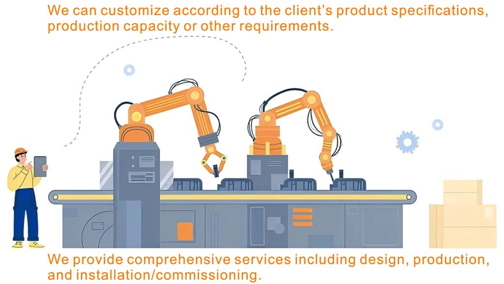
GGD AC Low Voltage Distribution Cabinet Assembly Line
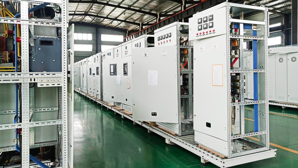
GGD is a fixed AC low-voltage distribution cabinet (AC) with 4 compartments: busbar, circuit breaker, cable inlet/outlet, and enclosure. Its assembly line adopts single-piece flow + zonal operation (designed as customized), covering 12 key steps from pre-production to packaging. Equipped with busbar processing, testing equipment and fixtures, it follows strict process, quality and safety standards, suitable for mass and on-site assembly, with small-batch and mass production options.
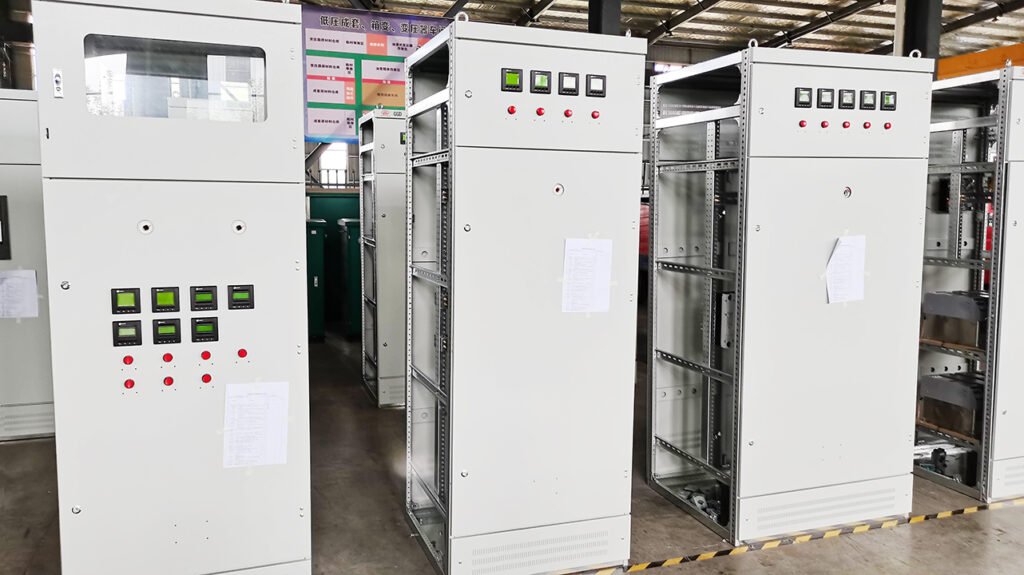
GGD AC Low Voltage Distribution Cabinet Structural Description
- Overview
GGD type AC low voltage distribution cabinet is a widely used fixed-type low voltage power distribution equipment, suitable for:
- Rated voltage: AC 400V and below or as customized
- Rated frequency: 50Hz or as customized
- Main applications: power distribution, motor control, lighting and power supply, power systems in factories, buildings and residential communitiesIt features a metal assembled frame with enclosed compartment design.
- Overall Structure (Top to Bottom)
The internal space of the GGD cabinet is divided into four functional areas:
① Top: Busbar Chamber (Main Busbar Area)
- Equipped with three-phase main busbars L1/L2/L3 + N neutral bar + PE earth bar
- Busbars are made of copper bars and fixed with insulating clamps
- Generally an independent compartment, isolated from other areas to prevent electric arcs and electric shocks
- Function: collects main power and distributes power to each circuit
② Middle: Circuit Breaker / Component Chamber (Main Circuit)
This is the core area of the GGD cabinet, where all main components are fixedly mounted on mounting plates. Common components include:
- Moulded case circuit breakers (MCCB) for incoming and outgoing lines
- Miniature circuit breakers (MCB) for branch circuits
- AC contactors
- Thermal relays (overload protection)
- Surge protective devices (SPD)
- Energy meters
- Transfer switchesComponents are fixed on mounting rails or mounting plates and are non-extractable, which is the key difference between GGD and withdrawable cabinets.
③ Lower: Cable Inlet & Outlet Chamber
Used for cable connection, mainly including:
- High-current power cables entering from the bottom or rear of the cabinet
- Terminal blocks (high-current terminals, control terminals)
- Independent PE earth bar and N neutral bar
- Cable clamps and cable organizersEnsures safe, neat and easy maintenance of wiring.
④ Enclosure and Door
- Frame is constructed of cold-rolled steel by assembly or welding
- Front door: usually a metal door with observation window and mechanical interlock
- Rear door / side panels are removable for easy maintenance
- Protection degree: IP30~IP40
- Safety Structural Design
- Compartment separation: busbar, main circuit and cable chambers are independently separated
- Interlock protection:
- Cabinet door is interlocked with circuit breakers; power cannot be supplied with door open
- Effectively prevents misoperation and electric shock
- Earthing system: cabinet body, door and mounting plates are reliably earthed
- Flame-retardant materials: partitions and accessories are mostly made of flame-retardant materials
- Insulation barriers: phase-to-phase and phase-to-earth isolation for improved safety
- Summary of GGD Structural Features
- Fixed installation type with simple structure
- Low cost and high reliability
- Easy maintenance and high space utilization
- Suitable for general industrial and civil power distribution applications
- Non-extractable components; circuit maintenance requires power cutoff
GGD AC Low-Voltage Power Distribution Cabinet Assembly Line Description
(Including Workstations, Processes, Equipment and Quality Control)
I. Assembly Line Positioning and Application Scenarios
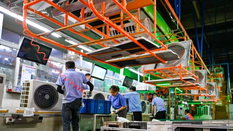
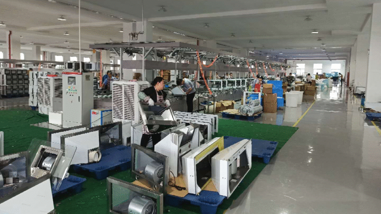
The GGD assembly line is a dedicated production line for fixed-type cabinets, designed with the concept of single-piece flow + zonal operation. Its daily production capacity is 80–120 units per shift (depending on workstation configuration or as customized). It covers the entire process from cabinet pretreatment, component assembly, busbar/cable wiring to testing and acceptance, suitable for mass factory production and on-site complete set assembly.
II. Core Workstations and Operation Flow (12 Key Steps)
| Workstation No. | Workstation Name | Core Operation Content | Key Standards |
|---|---|---|---|
| 1 | Pre-production Preparation & Drawing Verification | Verify cabinet type, number of circuits, component parameters (MCCB, contactor, instruments, etc.), material list (copper bars, cables, fasteners); confirm consistency of wiring diagrams and primary system diagrams | No errors or omissions in drawings; matching material models/quantities; clear identification |
| 2 | Cabinet Pretreatment | Inspect cabinet appearance (no deformation, paint peeling, opening deviation ≤1mm); correct mounting beams/columns; adjust door hinges/interlocks | Intact spray coating; aligned beam holes; smooth door opening/closing; effective interlocking |
| 3 | Structural Component Assembly | Assemble mounting beams/columns; install compartment partitions (busbar chamber / component chamber / cable chamber); fix PE/N busbar supports | Verticality ≤1.5mm/m; gap between grouped cabinets ≤2mm; firm partitions |
| 4 | Primary Component Installation | Install MCCB, air circuit breakers, knife switches, contactors, thermal relays, surge protective devices (SPD) on mounting plates per layout drawing | Component spacing ≥100mm; matching flashover distance; bolt tightening torque (M8/M10: 25–50N·m) |
| 5 | Busbar (Copper Bar) Processing & Assembly | Bend and punch copper bars per drawings; clean and apply conductive joint grease to lapped surfaces; install main busbars (L1/L2/L3/N/PE) in busbar chamber; connect busbars between cabinets | Tight and gap-free lapped surfaces; correct phase sequence (yellow/green/red/light blue/yellow-green); complete insulation sleeves/partitions |
| 6 | Secondary Component & Terminal Block Installation | Install energy meters, indicator lights, push buttons, control terminal blocks (e.g., Phoenix terminals); pre-install wire markers | Horizontal and firm instruments; neatly arranged terminal blocks; wire markers consistent with drawings |
| 7 | Primary Circuit Wiring | Route power cables from cabinet bottom/rear with bending radius ≥10× outer diameter; crimp copper lugs hydraulically; connect to breakers, busbars and terminal blocks | No loose connections or burrs in crimping; clear wire markers; correct phase sequence |
| 8 | Secondary Circuit Wiring | Lay control/signal wires in separate ducts (isolated from primary wires); connect point-by-point per wiring diagram; crimp cold-pressed terminals for 1.5–2.5mm² BVR wires | Neat routing without crossing; terminal torque 0.8–1.2N·m; no mixed or wrong connections |
| 9 | Grounding System Installation | Connect cabinet, door, mounting plate and foundation steel to grounding main busbar; strictly separate PE and N wires | Good grounding continuity; grounding resistance ≤4Ω (≤1Ω for critical locations) |
| 10 | Appearance Finishing | Clean interior (no debris or iron filings); heat-shrink wire markers; affix nameplates and primary system diagrams; inspect cabinet door sealing | No foreign matter; standard identification; intact sealing |
| 11 | Ex-Works Testing | Insulation resistance test (500V megohmmeter, main circuit ≥1MΩ); wiring verification; grounding test; switching on/off operation test | Qualified insulation; correct wiring; reliable operation |
| 12 | Finished Product Packaging & Warehousing | Wrap cabinet with protective film; mark cabinet number, circuits and parameters; store in warehouse | Intact packaging; clear identification; traceable records |
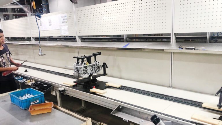
III. Key Equipment and Tool Configuration
1. Special Equipment
- Busbar processing line: 3-station busbar processing machine (bending/punching/shearing), copper bar tinning equipment
- Harness processing station: automatic wire stripper, terminal crimping machine, heat shrink gun
- Testing equipment: 500V megohmmeter, grounding resistance tester, calibrated torque wrench, multimeter
- Auxiliary equipment: anti-scratch forklift, bench drill, level gauge, plumb bob, electric drill
2. Tooling and Fixtures
Cabinet positioning fixtures (for grouped cabinet installation), PPO busbar supports, cable holders, cable management troughs
Special torque sockets (for M8/M10/M12 bolts), insulated operating rods, anti-electric shock face shields
IV. Core Process Points of the Assembly Line
- Compartment design: Strictly follow the principle of independent busbar chamber, separated from component and cable chambers by flame-retardant partitions to prevent arc spread.
- Busbar process: Clean lapped surfaces and apply conductive joint grease; tighten bolts to specified torque; insulation distance between phases and phase-to-ground ≥15mm.
- Wiring specification: Separate primary and secondary wires in different ducts; reserve 10–15mm margin for secondary wires, strip 4–6mm insulation, with uniform wire marker orientation.
- Interlock safety: Mechanical interlock between cabinet door and circuit breaker (closing prohibited when door is open, door opening prohibited when closed) to ensure operational safety.
- Grounding requirement: All metal parts reliably grounded; grounding main busbar connected to distribution room grounding grid at no less than 2 points.
V. Quality Control and Safety Specifications
- Full-process QC: Self-inspection / mutual inspection / special inspection at each step; 100% sampling inspection for key processes (busbar tightening, secondary wiring, grounding).
- Safety rules: De-energized operation throughout with “DO NOT SWITCH ON” tags; special supervision for live testing with insulated shoes and gloves; short-circuiting of protection devices strictly prohibited.
- Acceptance standards: Insulation resistance ≥1MΩ, grounding resistance ≤4Ω, effective door interlock, no abnormal noise/heating, complete and traceable identification.
VI. Typical Production Capacity and Layout Recommendations (OR as customized)
- Small-batch production line (5–10 units/day): mainly including “preparation + component assembly + wiring + testing”.
- Mass production line (80–120 units/day): mainly including “busbar processing, harness prefabrication, structural assembly, wiring, testing, etc.), 8–10 persons per shift. Prefabrication stations (copper bar and harness pre-processing” are configured to improve efficiency.