
This paper introduces that the motor is composed of stator, rotor and accessories, details the stator and rotor sub-assembly and final assembly processes, and covers multiple tests including insulation resistance measurement, no-load test and locked-rotor test. The motor assembly line is a standardized flow system, adopting a linear or U-shaped layout and divided into three functional zones. Following the logic of “sub-assembly first, final assembly second and inspection last”, it enables flexible mass production of motors with various frame sizes. Its automation level is customizable, and high quality is guaranteed through standard operating procedures (SOPs) and quality inspection nodes.
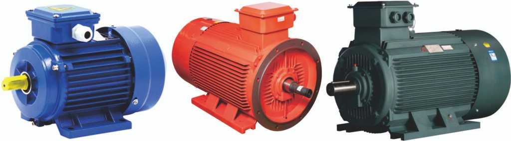
Three-phase Asynchronous Y-series Motors Assemly Line are suitable to Assemble/Produce Three-phase Asynchronous Y-series Motors. (If clients have more requirements or want to produce the other motors, welcome to contact us.)
Part I. Structure, Assembly and Testing Process of Three-phase Asynchronous Y-series Motors
Three-phase asynchronous Y-series motors are mainly composed of stator, rotor and other accessories. Below is an introduction to their structure, assembly process and testing process.
Structure
The stator of a three-phase asynchronous Y-series motor consists of stator core, stator winding and frame; the rotor consists of rotor core and rotor winding; other accessories include end covers, bearings, bearing end covers, fans, etc.
Assembly Process
- Stator Sub-assembly
- Place the frame on the workbench with the terminal box facing you and the right end facing upwards.
- Gently place the stator core inside the frame, align it properly with the lead wires facing upwards and aligned with the lead wire cavity of the frame. Ensure that the retaining slot avoids the fixing hole positions of the frame.
- Use a press-fitting tool and a hydraulic press to press the stator core into the frame, then install the end insulation sleeve.
- Drill stator core fixing holes, remove iron filings inside the holes, screw in the fixing screws and lifting eye bolts, and record the model and specifications.
- Use a wire hook to pull the lead wires into the lead-out holes of the frame, cut off the excess length, strip about 5mm of insulation, remove the end insulation sleeve, put on alkyd glass enamel tubes, connect the terminal lugs, crimp them tightly with a cold-pressing pliers, and then pull the glass enamel tubes down to cover the crimped joints.
- Fix the terminal box base and terminal board on the frame, fasten the lead wires to the terminal board, and finally clean the inner cavity of the stator with compressed air and a brush, then place the stator on the assembly workbench.
- Rotor Sub-assembly
- Put the bearing caps on the painted rotor ends, and then mount the bearings on both ends, ensuring that the inner and outer rings of the bearings face the same direction.
- Place the rotor on the cushion tire of the bearing press-fitting machine, slowly press or gently drive the bearings into place with a bearing sleeve, and apply a small amount of lubricating oil to the bearing journals on the shaft during press-fitting.
- Final Assembly
- Check for any damage to the insulation of the winding end wires, and repair any exposed copper parts in accordance with requirements.
- Install the end covers on the rotor shaft, generally place wave spring washers on the shaft extension end, then pre-tighten the fixing bolts of the motor end covers and bearing end covers at both ends. If there is any deviation between the end cover holes and the frame fixing holes, it is allowed to correct them with a hand hammer.
Testing Process
The testing of three-phase asynchronous Y-series motors can be carried out with the specific steps as follows:
- Test Preparation: Verify the basic parameters such as the model and specifications of the motor, conduct an appearance inspection, and check the integrity and accuracy of the test equipment and instruments.
- Insulation Resistance Measurement: Use a megohmmeter to measure the insulation resistance between the windings and the ground, and between each phase winding under cold and hot conditions, which should meet the requirements of relevant standards.
- No-load Test: Apply the rated voltage to the motor to make it run under no-load condition, measure the three-phase no-load current, whose unbalance rate should comply with the specified limits, and observe the operating status of the motor for any abnormal vibration, noise, etc.
- Locked-rotor Test: Block the rotor of the motor to prevent it from rotating, apply an appropriate voltage, and measure parameters such as locked-rotor current and locked-rotor torque.
- Load Test: Apply the rated load to the motor and run it until it reaches thermal stability, measure parameters such as the output power, current, voltage, speed, efficiency and power factor of the motor.
- Temperature-rise Test: Direct load method, equivalent load method or loss analysis method can be adopted to verify whether the temperature rise of the motor during continuous operation under rated load meets the standard requirements, and evaluate its heat dissipation performance and thermal stability.
- Other Tests: Depending on the needs, short-time overload capacity test, vibration test, noise test, dielectric withstand voltage test, electromagnetic compatibility test, etc. can also be performed.
Part II. Brief Introduction to the Assembly Line of Three-phase Asynchronous Y-series Motors
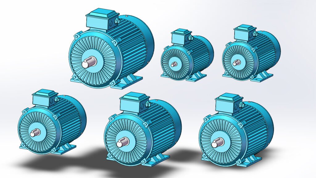
The assembly line of three-phase asynchronous Y-series motors is a set of standardized and streamlined production operation system, specially designed to complete the whole process from component sub-assembly, final machine assembly to inspection of Y-series motors. With the core design principles of “high efficiency, precision and stability”, this assembly line is suitable for the mass production of three-phase asynchronous motors with different power ranges (such as frame sizes Y80, Y90, Y100, etc.), and is widely applied in the field of general motor manufacturing.
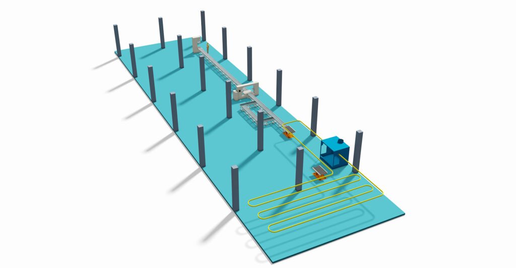
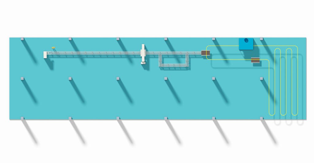
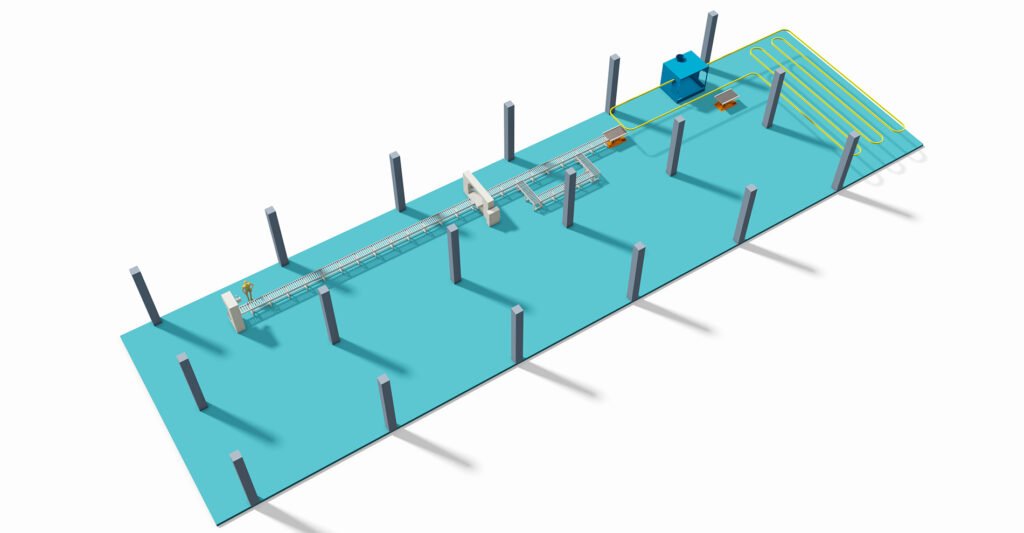
Overall Layout of the Assembly Line
The assembly line usually adopts a linear or U-shaped layout, which is divided into three functional zones according to the process flow. All zones are connected by conveying lines (such as roller lines, belt lines, overhead chains) to realize the orderly circulation of components and semi-finished products:
- Sub-assembly and Pre-treatment Zone: It includes stator sub-assembly stations, rotor sub-assembly stations and accessory preparation stations, where the preliminary processing of core components is completed.
- Final Assembly Core Zone: As the core section of the assembly line, it is equipped with key stations such as stator press-fitting, rotor assembly, end cover assembly, bearing lubrication and installation.
- Inspection and Post-treatment Zone: It covers semi-finished product inspection, complete machine testing, appearance finishing and packaging stations to ensure that the ex-factory motors meet the quality standards.
Core Process Flow
The assembly line strictly follows the operation logic of “first sub-assembly, then final assembly, and finally inspection”. The main content of each process is as follows:
- Sub-assembly and Pre-treatment Process
- Stator sub-assembly: Complete operations such as pressing the stator core into the frame, embedding and shaping the stator windings, welding and insulating the lead wires, and installing the terminal box to form a qualified stator assembly.
- Rotor sub-assembly: Complete operations such as press-fitting the rotor core and rotating shaft, inspecting the rotor windings (cast-aluminum rotor for squirrel-cage type), pressing and lubricating the bearings, and installing the fan blades to form a qualified rotor assembly.
- Accessory preparation: Clean and screen accessories such as end covers, bearing end covers, sealing rings and fasteners to ensure they are free from defects and match the specifications.
- Final Assembly Core Process
- Stator assembly positioning: Fix the stator assembly on the fixture to ensure the inner cavity is clean and free from impurities.
- Rotor assembly installation: Smoothly install the rotor assembly into the stator inner cavity, adjust the air gap between the stator and rotor to be uniform, and avoid scratching the windings.
- End cover assembly: Install the front and rear end covers in sequence, tighten the end cover bolts, adjust the bearing preload, and ensure the rotor rotates flexibly without jamming.
- Accessory installation: Install accessories such as fans, fan covers and terminal box covers to complete the initial assembly of the whole machine.
- Inspection and Post-treatment Process
- Semi-finished product inspection: Test indicators such as insulation resistance, bearing rotation noise and stator-rotor coaxiality, and reject unqualified products.
- Complete machine performance testing: Conduct no-load test, locked-rotor test, temperature-rise test, etc., and record the motor operation parameters.
- Post-treatment and packaging: Perform appearance cleaning, paint touch-up and nameplate pasting on qualified motors, and finally carry out moisture-proof packaging and warehousing.
Characteristics of the Assembly Line
- Strong compatibility: By replacing the fixtures, it can adapt to the assembly of Y-series motors with different frame sizes, realizing flexible production.
- Customizable automation level: Small motor assembly lines can adopt a combination of manual and semi-automatic equipment; medium and large motor assembly lines can be equipped with automatic press-fitting machines, automatic tightening machines, online testing systems, etc., to improve production efficiency.
- High quality controllability: Quality inspection nodes are set at each station, and standard operating procedures (SOPs) are adopted to ensure each process meets the technical requirements and reduce human errors.
We can customize according to the client’s product specifications, production capacity or other requirements.
We provide comprehensive services including design, production, and installation/commissioning.