
Household Pump Assembly and Production Solutions
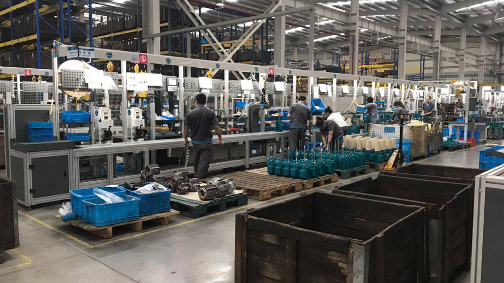
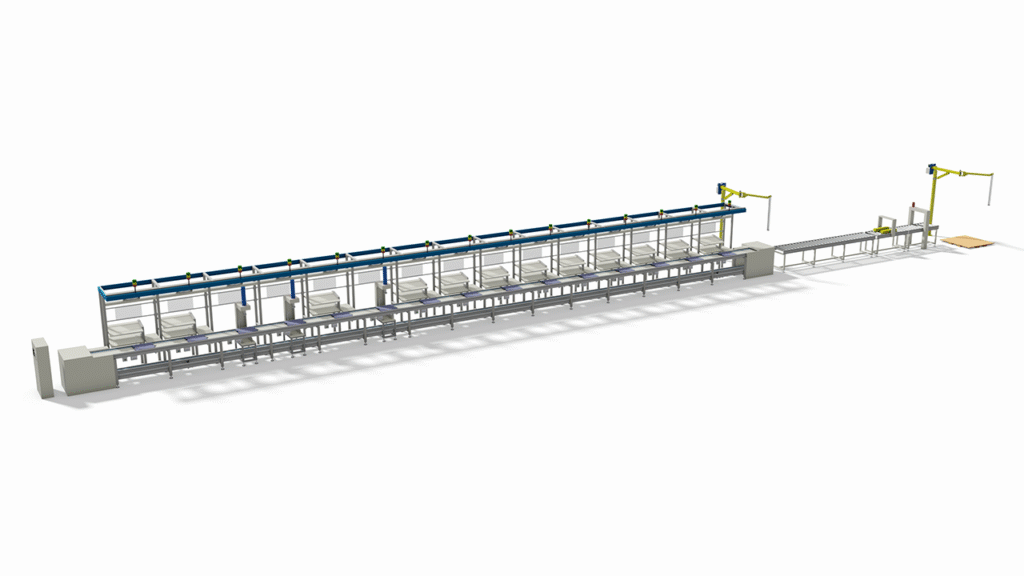
Our multi-functional assembly lines are designed for the efficient production of a wide range of water pumps, including household pumps, garden pumps, small submersible pumps, self-priming centrifugal pumps, and transfer pumps. The core process employs a precision assembly workflow, starting from sub-assembly tasks such as rotor dynamic balancing and motor assembly, progressing through the critical pump head station for mechanical seal and impeller installation, and concluding with final integration. This is complemented by a comprehensive quality control system, which includes incoming inspection, in-line electrical testing, and 100% final performance testing (covering key indicators such as self-priming capability and leak detection). The assembly line production mode is ideally suited for high-volume, standardized products, delivering outstanding performance in efficiency, consistency, and quality control. We are committed to providing tailored production solutions to meet diverse manufacturing needs.
Household Pumps Assembly Lines are suitable to Assemble/Produce Household Pumps, Garden Pumps, Small Submersible Pumps, Self-Priming Centrifugal Pumps, Water Transfer Pumps and so on. (If clients have more requirements or want to produce the other pumps, welcome to contact us.)
Part I: Structure, Assembly, and Testing Process for Household Pumps
I. Structure
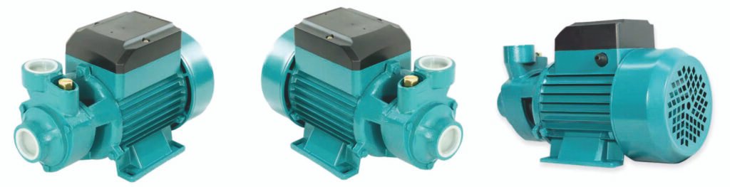
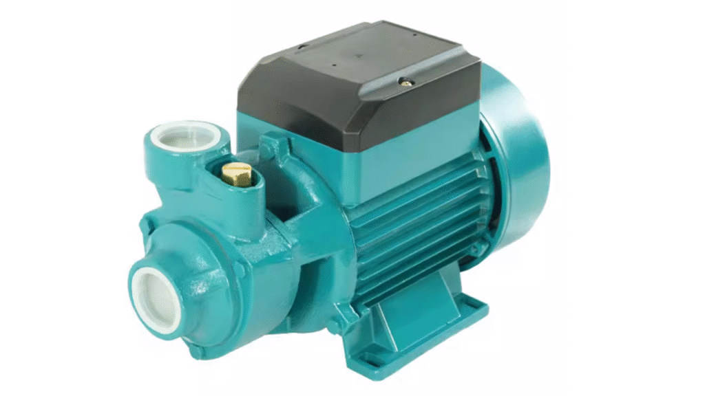
The garden pump (self-priming centrifugal pump) is primarily composed of the following components, with its structural design balancing efficiency, self-priming capability, and durability.
1. Power Components
- Motor: Typically a single-phase AC induction motor (220V), Totally Enclosed, Fan-Cooled (TEFC). This is the core power source of the pump.
- Shaft: A stainless steel or stainless-clad steel shaft that connects the motor rotor to the impeller, transmitting torque.
- Bearings: Support the pump shaft, usually deep groove ball bearings, ensuring smooth rotation.
2. Hydraulic Components
- Pump Casing (Volute): Typically made of cast iron, cast aluminum, or engineering plastic (e.g., PP). Its volute-shaped flow passage is designed to convert the kinetic energy generated by the impeller into pressure energy.
- Impeller: Often a closed or semi-open impeller, made from engineering plastic (e.g., reinforced nylon) or bronze/stainless steel. It is the core component that generates centrifugal force and water flow.
- Mechanical Seal: One of the most critical components, located where the pump shaft enters the pump chamber. It prevents high-pressure water from leaking along the shaft into the motor. It is usually made of hard materials like silicon carbide/ceramic.
- Inlet & Outlet Ports: Standard threaded ports (e.g., G1″), for connecting garden hoses.
3. Self-Priming and Air Release Components (Key to achieving “self-priming” functionality)
- Air-Water Separation Chamber: A cavity in the upper part of the pump casing used to separate the drawn-in air and water, allowing air to be expelled and water to recirculate.
- Check Valve (Non-Return Valve): Usually located inside the inlet port or below the impeller. It closes when the pump stops, retaining water in the pump chamber and suction line, which is crucial for quick priming during the next start.
4. Auxiliary and Safety Components
- End Cover/Seal Cover: Used to secure the mechanical seal and bearing housing.
- Casing Seals (O-Rings): Ensure static sealing at the connection faces of the pump casing.
- Overheat Protector: Built into the motor to prevent burnout due to dry running, etc.
- Housing and Bracket: Protect the internal structure and provide mounting support.
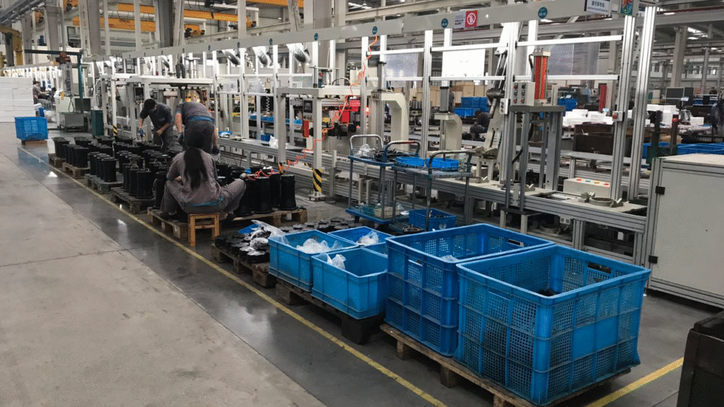
II. Assembly Process
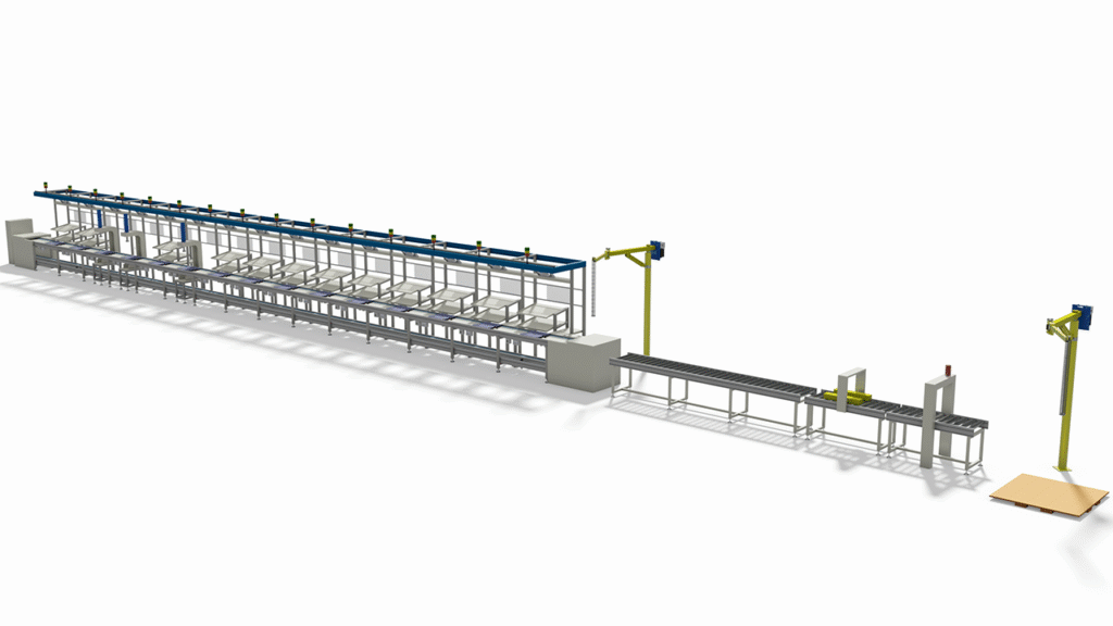
The assembly process follows the principle of proceeding from the inside out, prioritizing precision components, and is typically carried out on an assembly line.
1. Rotor Sub-Assembly Line
- Press-Fitting: Pressing the bearings onto the shaft ends of the motor rotor.
- Dynamic Balancing Test: Performing dynamic balance correction on the rotor to ensure smooth high-speed operation, reducing vibration and noise.
2. Motor Sub-Assembly Line
- Stator and Housing Assembly: Pressing the stator into the motor housing.
- Rotor Installation: Installing the balanced rotor assembly into the housing containing the stator.
- End Cover Installation: Fixing the motor rear end cover, attaching the cooling fan and fan cover.
3. Pump Head Sub-Assembly Line (Critical Station)
- Mechanical Seal Installation: Pressing the stationary ring of the mechanical seal into the seal seat of the pump casing, and fitting the rotating ring onto the shaft. This is the critical leak-prevention station, requiring a clean environment.
- Impeller Installation: Fitting the impeller onto the shaft, securing it with an impeller nut or bolts, and adding a lock washer.
- Check Valve Installation: Installing the check valve assembly into the inlet port chamber.
4. Final Assembly Line
- Joining: Aligning and fastening the assembled pump head unit with the motor unit using long bolts.
- Installing inlet/outlet port fittings.
- Installing housing, nameplate, grounding screw, etc.
- Final Torquing: Using torque-controlled wrenches to tighten all bolts to standardized specifications.
III. Testing Process
Every pump must undergo strict testing before leaving the factory to ensure performance and safety. Testing is typically divided into the following stages:
1. Incoming Quality Control (IQC)
- Sampling inspection of key purchased components (motor, impeller, mechanical seal, sealing rings, etc.) for dimensions, material, and appearance.
2. In-Line Testing (Critical Stations)
- Insulation Resistance Test: After motor assembly, testing the insulation resistance between live parts and the housing (typically > 50 MΩ).
- High-Potential (Hipot) Test: Applying a high voltage (e.g., 1800V AC) to verify insulation strength. No breakdown is acceptable.
3. Final Factory Testing (100% Inspection)
This is the final checkpoint for quality control. The test line typically includes:
- Run Test: Starting the pump unloaded, listening for abnormal noise/vibration, checking rotation direction.
- Self-Priming Performance Test: Simulating user conditions. Drawing air from a specified height (e.g., suction lift of 8 meters) and measuring the time required to achieve rated flow or establish stable pressure (priming time), which must be within a specified limit (e.g., several minutes).
- Performance Test (Core):
- Conducted on a standard test bench.
- Flow-Head Curve: By adjusting the outlet valve, measuring the head (pressure) at different flow points to ensure conformity with the design curve.
- Maximum Head (Shut-off Head) Test: Closing the outlet to test the maximum pressure the pump can achieve.
- Input Power/Current Test: Ensuring the motor load is normal under rated operating conditions.
- Leak Test:
- Dry Test: Using an air pressure leak test, filling the pump chamber with pressurized gas and detecting pressure drop.
- Wet Test: After the performance test, checking all joints and the shaft seal for seepage or dripping (a minimal film of moisture is permissible at the mechanical seal, but no droplets).
- Final Inspection: Appearance, accessories, labeling, and packaging check.
4. Type Testing / Reliability Testing (Sampling or New Product Validation)
- Life Test: Continuous operation for hundreds to thousands of hours under rated conditions.
- On/Off Cycle Test: Simulating frequent starts and stops.
- Sandy Water Test: Testing pump wear in water containing minor impurities.
- Salt Spray Test: Checking the corrosion resistance of metal parts.
Part II. Comparison of Garden Water Pump Production: Assembly Line vs. Non-Assembly Line
Here is a clear comparison of the key differences between producing garden water pumps using an assembly line versus non-assembly line methods (e.g., cell-based or fixed-station assembly), analyzed across multiple dimensions.
| Comparison Dimension | Production Using an Assembly Line | Production Without an Assembly Line |
|---|---|---|
| Core Definition | Flow-line operation where the pump body moves on a conveyor or track, and workers/machines at fixed stations complete specific assembly steps. | Cell-based or fixed-station assembly, where most or all assembly of an entire pump is completed by the same group of workers at one or a few stations. |
| Production Mode | Push-based, continuous/cycled. Organized according to a predetermined cycle time, emphasizing line balancing. | Pull-based, batch/discrete. Assembly is performed in batches based on orders or plans. |
| Efficiency & Output | High. Specialized division of labor reduces walking and tool-fetching time. Suitable for high-volume production of standardized products. | Lower. Operators need to perform multiple tasks with longer changeover times. Suitable for low-volume, high-mix, or customized production. |
| Quality Control | In-line, immediate. Inspection points can be set after key stations (e.g., after dynamic balancing test, after seal installation). Issues can be quickly traced to a specific process and responsible personnel. | Relies mainly on final inspection. Quality issues are often only discovered after complete assembly, making root cause tracing difficult. Heavily dependent on the individual skill and responsibility of the assembler. |
| Skill Requirements | Lower and specialized. Workers typically only need to master a few specific operations. Training cycle is short. | Higher and comprehensive. Workers must master all assembly steps and techniques for the entire pump. Requires “master craftsman” type talent. Training cycle is long. |
| Consistency | High. Processes, tools, and torque are strictly defined and executed. Products have a high degree of standardization and interchangeability. | Lower. Relies on personal experience and habits. There may be subtle variations between products assembled by different workers or in different batches. |
| Work-in-Progress & Logistics | Low and fast-moving. Materials are delivered to the line side according to the cycle time. The amount of WIP is fixed and low. | High and堆积. Materials must be delivered as kits to the station and remain occupied for the entire pump assembly cycle. |
| Flexibility | Low. The line is designed for specific products. Switching models requires line stoppage, layout, and tooling adjustments, which is costly. | High. Stations are highly versatile and can adapt to assembling different models without complex adjustments, allowing flexible changeovers. |
| Initial Investment | High. Requires dedicated conveyor lines, specialized fixtures, and may include automation (e.g., automatic screwdrivers). | Low. Main investment is in general-purpose tools, workbenches, and material racks. |
| Typical Application Scenario | Mainstream garden pump and standardized household pump product lines of large manufacturers, pursuing economies of scale. | Special models, small-batch orders, prototype builds, repair part assembly, or very small workshop-style factories. |
Summary
- The core drivers for choosing an assembly line are scale, efficiency, and consistency. It achieves cost reduction, efficiency gains, and stable quality by decomposing complex processes into simple steps, marking large-scale industrial production.
- The core advantages of not using an assembly line are flexibility and low initial investment. It relies on the comprehensive skills of workers to adapt to change, offering greater advantages for small batches, high variety, or during the startup phase.
We can customize according to the client’s product specifications, production capacity or other requirements.
We provide comprehensive services including design, production, and installation/commissioning.